Table of Contents
Advertisement
Quick Links
AN2019_09 EVAL-C101T-IM231 User manual
EVAL-C101T-IM231 User manual
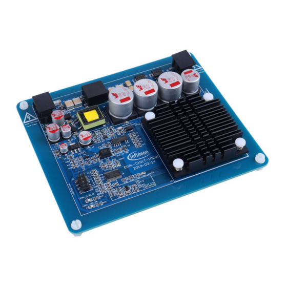
Motor Drive Evaluation Board Based On IMC101T-T038 and IM231-L6S1B
About this document
Scope and purpose
This user manual provides an overview of the evaluation board EVAL-C101T-IM231 including its main features,
key data, pin assignments and mechanical dimensions.
EVAL-C101T-IM231 is an evaluation-board as part of the evaluation design platform for motor drive based on
iMOTION™2.0 IMC100 Series. This board features and demonstrates Infineon's advanced Motion Control Engine
(MCE) technology for permanent magnet motors drive over the full speed range. In the same time it features
and demonstrates Infineon's CIPOS
The evaluation board EVAL-C101T-IM231 was developed to support customers during their first steps designing
applications with running any permanent magnet motor via sensor-less sinusoidal control.
Intended audience
This user manual is intended for all technical specialists working with the EVAL-C101T-IM231 board under
laboratory conditions.
Table of Contents
About this document ....................................................................................................................... 1
Table of Contents ........................................................................................................................... 1
1
Safety precautions ......................................................................................................... 2
2
Introduction .................................................................................................................. 3
3
Main features ................................................................................................................ 4
3.1
Key data ................................................................................................................................................... 5
3.2
3.3
Setting up the system.............................................................................................................................. 8
3.4
System debug process ............................................................................................................................ 9
3.5
MCEWizard setup overview ................................................................................................................... 10
3.6
MCEDesigner setup overview ................................................................................................................ 13
4
Pin assignments ........................................................................................................... 15
5
Schematics and Layout .................................................................................................. 16
5.1
EMI filter circuit ...................................................................................................................................... 16
5.2
5.3
IMC101T-T038 Schematic Overview ..................................................................................................... 18
5.4
Auxiliary power supply .......................................................................................................................... 19
5.5
Inverter over current protection circuit................................................................................................ 19
5.6
PCB Layout ............................................................................................................................................ 20
6
Bill of Materials of EVAL-C101T-IM231 ............................................................................. 22
7
Reference .................................................................................................................... 25
Revision History ............................................................................................................................ 26
User manual
www.infineon.com
Micro IPM technology for motor drive.
TM
Micro IPM............................................................................................. 17
Please read the Important Notice and Warnings at the end of this document
<Revision 1.0>
<2019-07-30>
Advertisement
Table of Contents

Related Manuals for Infineon Technologies EVAL-C101T-IM231


Summary of Contents for Infineon Technologies EVAL-C101T-IM231
-
Page 1: Table Of Contents
This user manual provides an overview of the evaluation board EVAL-C101T-IM231 including its main features, key data, pin assignments and mechanical dimensions. EVAL-C101T-IM231 is an evaluation-board as part of the evaluation design platform for motor drive based on iMOTION™2.0 IMC100 Series. This board features and demonstrates Infineon’s advanced Motion Control Engine (MCE) technology for permanent magnet motors drive over the full speed range. -
Page 2: Safety Precautions
Table 1 Precautions Caution: The ground potential of the EVAL-C101T-IM231 system is biased to a negative DC bus voltage potential. When measuring voltage waveform by oscilloscope, the scope’s ground needs to be isolated. Failure to do so may result in personal injury or death, and equipment damage. -
Page 3: Introduction
(with sensor less field oriented control), 3-phase output to motor. It is single shunt for current sensing and a voltage divider for DC-link voltage measurement. The EVAL-C101T-IM231 evaluation board is available from Infineon. The features of this board are described in the design feature chapter of this document, whereas the remaining paragraphs provide information to enable the customers to copy, modify and qualify the design for production according to their own specific requirements. -
Page 4: Main Features
Motor Drive Evaluation Board Based On IMC101T-T038 and IM231-L6S1B Main features Main features EVAL-C101T-IM231 is a complete evaluation board including IMC101T-T038 controller and a 3 phase Micro IPM for motor control application. The kit demonstrates Infineon’s motion control IC and IPM technology for motor drives. -
Page 5: Key Data
EVAL-C101T-IM231 User manual Motor Drive Evaluation Board Based On IMC101T-T038 and IM231-L6S1B Main features Main features of CIPOSTM Micro IPM-IM231-L6S1B are: • 600 V 3-phase inverter including gate drivers & bootstrap function • Low VCE(sat) TRENCHSTOP™ IGBT6 • Temperature monitor •... - Page 6 EVAL-C101T-IM231 User manual Motor Drive Evaluation Board Based On IMC101T-T038 and IM231-L6S1B Main features Figure 3 provides pinout of the IMC101T-T038. The following drawings give the position of the functional pins for the available packages. HALL2/AIN3 HALL1/AIN4 IW/AHALL1-/AIN2 REFW/AHALL1+/AIN1 IV/AHALL2-...
- Page 7 EVAL-C101T-IM231 User manual Motor Drive Evaluation Board Based On IMC101T-T038 and IM231-L6S1B Main features Table 2 depicts the important specifications of the evaluation board EVAL-C101T-IM231. Table 2 EVAL-C101T-IM231 board specifications Parameters Values Conditions / comments Input Lower AC input, less motor power...
-
Page 8: The Relationship Between I
Figure 5 the picture is showing the relationship between I (3 phase output current) and PWM Frequency, The curves can be used as a reference to output current capability of the evaluation board when you use it. & F @Tc=100 ℃,Rthca=10.7℃/W For EVAL-C101T-IM231 6, 1.5 10, 1.17 15, 0.97 20, 0.92... -
Page 9: System Debug Process
EVAL-C101T-IM231 User manual Motor Drive Evaluation Board Based On IMC101T-T038 and IM231-L6S1B Main features Figure 6 points out the functional groups on the top side of the EVAL-C101T-IM231 evaluation board. 1. J1 - AC Line connector 2. EMI filter 3. Rectifier 4. -
Page 10: Mcewizard Setup Overview
EVAL-C101T-IM231 User manual Motor Drive Evaluation Board Based On IMC101T-T038 and IM231-L6S1B Main features Figure 7 the picture is showing the application system connection. Motor Phase Outputs Figure 7 System connection indication STEP1: Download Firmware to IMC101T (1) Connect iMOTION Link to J2. - Page 11 EVAL-C101T-IM231 User manual Motor Drive Evaluation Board Based On IMC101T-T038 and IM231-L6S1B Main features After selecting the MADK control and the power board, start the MCEWizard system setup procedure by clicking the “Next” button in the right bottom corner as shown in Figure 8.
- Page 12 EVAL-C101T-IM231 User manual Motor Drive Evaluation Board Based On IMC101T-T038 and IM231-L6S1B Main features Page Parameter Value Comment Script Coding Script File Operation and Script Refer to the “Reference Manual” Text Edit and the “Application Guide” Note: Please refer to the following link for more detailed information about Edit Script File.
-
Page 13: Mcedesigner Setup Overview
EVAL-C101T-IM231 User manual Motor Drive Evaluation Board Based On IMC101T-T038 and IM231-L6S1B Main features MCEDesigner setup overview After installing MCEDesigner installer, there is a shortcut for MCEDesigner on Windows desktop. Double click the shortcut to open MCEDesigner and then open “IMC101T_xx.irc” file. - Page 14 EVAL-C101T-IM231 User manual Motor Drive Evaluation Board Based On IMC101T-T038 and IM231-L6S1B Main features speeds, modify drive parameters and many other functions. Please refer to the MCEDesigner documentation for more details. To program new firmware and Drive System Parameter into IMC101T-T038, please click “Tools” menu and select “Programmer”...
-
Page 15: Pin Assignments
Motor Drive Evaluation Board Based On IMC101T-T038 and IM231-L6S1B Pin assignments Pin assignments General information about the connectors of the EVAL-C101T-IM231 evaluation board is described below. Table 4 provides the pin assignments of the J2. Table 4 J2-iMOTION Link interface S. -
Page 16: Schematics And Layout
Motor Drive Evaluation Board Based On IMC101T-T038 and IM231-L6S1B Schematics and Layout Schematics and Layout To meet individual customer requirements and make the EVAL-C101T-IM231 evaluation board a basis for development or modification, all necessary technical data like schematics, layout and components are included in this chapter. -
Page 17: Inverter Section Using Cipos
EVAL-C101T-IM231 User manual Motor Drive Evaluation Board Based On IMC101T-T038 and IM231-L6S1B Schematics and Layout Inverter section using CIPOS Micro IPM Inverter section are implemented using the CIPOS Micro IPM as sketched in Figure 14. The CIPOS module includes 600 V 3-phase inverter including gate drivers & bootstrap function, and low VECTRENCHSTOP IGBT6. -
Page 18: Imc101T-T038 Schematic Overview
Motor Drive Evaluation Board Based On IMC101T-T038 and IM231-L6S1B Schematics and Layout IMC101T-T038 Schematic Overview Figure 15 shows the schematic of EVAL-C101T-IM231 evaluation board with IMC101T-T038 controller. Figure 15 The schematics for the EVAL-C101T-IM231 evaluation board User manual <Revision 1.0>... -
Page 19: Auxiliary Power Supply
Schematics and Layout Auxiliary power supply Figure 16 depicts the schematic of the auxiliary power supply available on the EVAL-C101T-IM231 board. The circuit includes the latest CoolSET 5 of Infineon and fly back topology, directly output 15V and 3.3V. V connected to the gate drivers inside the CIPOS™... -
Page 20: Pcb Layout
Figure 18 illustrates the top assembly print of the evaluation board. Figure 18 Top overlay print of the EVAL-C101T-IM231 evaluation board Figure 19 depicts the bottom assembly print of the evaluation board. Figure 19 Bottom overlay print of the EVAL-C101T-IM231 evaluation board User manual <Revision 1.0> <2019-07-30>... - Page 21 Schematics and Layout The top layer routing of the PCB is provided in Figure 20. Figure 20 Top layer routing of the EVAL-C101T-IM231 Figure 21 illustrates the bottom layer routing of the PCB. Figure 21 Bottom layer routing of the EVAL-C101T-IM231 User manual <Revision 1.0>...
-
Page 22: Bill Of Materials Of Eval-C101T-Im231
EVAL-C101T-IM231 User manual Motor Drive Evaluation Board Based On IMC101T-T038 and IM231-L6S1B Bill of Materials of EVAL-C101T-IM231 Bill of Materials of EVAL-C101T-IM231 Table 7 provides the complete bill of materials for the EVAL-C101T-IM231 board. Table 7 Bill of materials Part description... - Page 23 EVAL-C101T-IM231 User manual Motor Drive Evaluation Board Based On IMC101T-T038 and IM231-L6S1B Bill of Materials of EVAL-C101T-IM231 Part description Designator Part Number Manufacturer DIODE GEN PURP 1KV 1A Vishay Semiconductor US1M-E3/61T DO214AC Diodes Division DIODE SCHOTTKY 45V 1.5A Vishay Semiconductor...
- Page 24 EVAL-C101T-IM231 User manual Motor Drive Evaluation Board Based On IMC101T-T038 and IM231-L6S1B Bill of Materials of EVAL-C101T-IM231 Part description Designator Part Number Manufacturer RES SMD 1/10W 48.7Kohm F 0805 R16, R34 RC0805FR-074K87L Yageo RES SMD 0ohm 1/8W 0805 RC0805JR-070RL Yageo RES SMD 1.5Kohm 1/8W 0805...
-
Page 25: Reference
EVAL-C101T-IM231 User manual Motor Drive Evaluation Board Based On IMC101T-T038 and IM231-L6S1B Reference Reference [1] Datasheet of Infineon-IMC100-DS-v01_03-EN [2] Datasheet of Infineon-IM231-L6S1B_T2B-DS-v02_00-EN [3] 2018-11_AN2018-36_EVAL-M1-IM231-A User Manual_V1.0_EN Note: Above all reference materials are available for download on Infineon’s website http://www.infineon.com/iMOTION User manual <Revision 1.0>... -
Page 26: Revision History
EVAL-C101T-IM231 User manual Motor Drive Evaluation Board Based On IMC101T-T038 and IM231-L6S1B Revision History Revision History Major changes since the last revision Version number Revision Date Revision description 2019-07-30 First release User manual <Revision 1.0> <2019-07-30>... - Page 27 Infineon Technologies office description or warranty of a certain functionality, (www.infineon.com).
Need help?
Do you have a question about the EVAL-C101T-IM231 and is the answer not in the manual?
Questions and answers