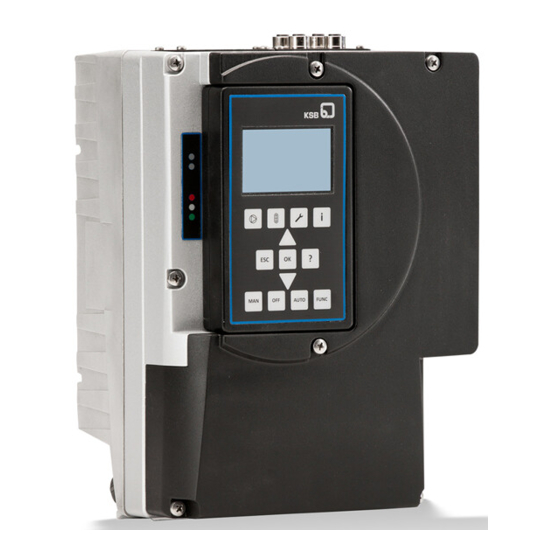
KSB PumpDrive 2 Supplementary Operating Manual
Modbus rtu module
Hide thumbs
Also See for PumpDrive 2:
- Installation & operating manual (213 pages) ,
- Supplementary operating manual (16 pages)
Summary of Contents for KSB PumpDrive 2
- Page 1 Field Bus Module Modbus RTU Module PumpDrive 2 PumpDrive 2 Eco Supplementary Operating Manual...
- Page 2 All rights reserved. The contents provided herein must neither be distributed, copied, reproduced, edited or processed for any other purpose, nor otherwise transmitted, published or made available to a third party without the manufacturer's express written consent. Subject to technical modification without prior notice. © KSB SE & Co. KGaA, Frankenthal 18/09/2020...
-
Page 3: Table Of Contents
Contents Contents Supplementary Operating Manual ....................... 4 General................................ 4 Field bus module connections ......................... 4 Installing the field bus module........................ 4 Connecting the field bus module ........................ 6 Modbus RTU module............................ 6 Modbus RTU protocol ............................ 9 Modbus RTU Module 3 of 20... -
Page 4: Supplementary Operating Manual
Table 1: Relevant operating manuals Type series Reference number of the installation/ operating manual PumpDrive 2 4074.81 PumpDrive 2 Eco 4074.82 1.2 Field bus module connections The field bus modules are plug-in modules. Fig. 1: Field bus module Table 2: Field bus module... - Page 5 1 Supplementary Operating Manual Blind cover Fig. 2: Blind cover Blind cover 1. Unscrew the cross recessed head screws in the blind cover. 2. Remove the blind cover. Field bus module 1. Carefully insert the field bus module into the open slot. The plug-in module is guided on rails until it engages in the contact.
-
Page 6: Connecting The Field Bus Module
1 Supplementary Operating Manual 1.4 Connecting the field bus module Observe the following when connecting the field bus module: ▪ Before the bus connection is established among the nodes, potential equalisation must have been implemented and checked. ▪ For high-frequency shielding, use shielded cables and assemble according to EMC requirements. - Page 7 1 Supplementary Operating Manual A cable specified for Modbus modules that has the following properties must be used as a connecting cable: ▪ Flexible ▪ Shielded ▪ Twisted wires for the data line (D0-D1) ▪ The wave impedance should be at least 100 Ohm. ▪...
- Page 8 1 Supplementary Operating Manual 1 2 3 4 5 1 2 3 4 5 1 2 3 4 5 1 2 3 4 5 Shielding Fig. 8: Wiring diagram Bus terminator The terminating resistors must conform to the following standard: Profibus standard DP DIN 19245, part 3, section 6.3.
-
Page 9: Modbus Rtu Protocol
4074.803/08-EN 1.6 Modbus RTU protocol Table 5: Address range of system (0000 - 00FF) 0000 Modbus Status DWORD 32-bit bit System Status System connection OK field Pump 1 online Pump 2 online Pump 3 online Pump 4 online Pump 5 online Pump 6 online 0002 System Alerts DWORD 32-bit bit... - Page 10 0028 Maximum Number of 3-7-2 DWORD UINT32 System Control r, w Pumps Running 002A Control Point 3-6-2 DWORD ENUM System Control r, w Local Field bus 002C Actual Value Source 3-6-3 DWORD ENUM System Control r, w Local Field bus 002E Actual Value (Closed-loop 1-2-3-1 DWORD Float32...
- Page 11 4074.803/08-EN 0064 Type of Control 3-6-1 DWORD ENUM System Control Suction pressure Differential pressure Differential pressure (sensorless) Flow rate Temperature (cooling) Temperature (heating) Suction-side level Discharge-side level Flow rate (sensorless) 0066 Fixed Speed Percent 3-6-5-1 DWORD Float32 In % of the speed value System Control range 0068-...
- Page 12 0102 Pump Alerts DWORD 32-bit bit Pump Status Thermal motor protection field Overvoltage Undervoltage Phase failure, motor side Short circuit Hardware fault Heat sink temperature high PCB temperature high Overcurrent Braking resistor Dynamic overload protection Firmware update required Dry running Dry running (external) Hydraulic blockage No master control...
- Page 13 4074.803/08-EN 0106 Pump Warnings DWORD 32-bit bit Pump Status Resonance range field Broken wire Actual value failure Hydraulic blockage Part load Overload Heat sink temperature high PCB temperature high Current high Current low Speed monitoring Frequency high Frequency low Power high Power low Limited stop ramp 24 V overload...
- Page 14 0112 Reserved Pump Control 0114 Speed 1-2-1-1 DWORD Float32 Speed Pump Process Variable 0116 Motor Input Power 1-2-1-2 DWORD Float32 Output base unit Pump Process Variable 0118 Pump Input Power 1-2-1-3 DWORD Float32 Output base unit Pump Process Variable 011A Pump Set Input Power 1-2-1-4 DWORD Float32 Output base unit...
- Page 15 4074.803/08-EN 0144 Reserved - 014F 0150 Digital Input Status 1-2-4-6 DWORD 32-bit bit Pump Process Variable field 0152 Analog Input 1 Value 1-2-4-1 DWORD Float32 Percent Pump Process Variable 0154 Analog Input 2 Value 1-2-4-2 DWORD Float32 Percent Pump Process Variable 0156 Analog Input 3 Value 1-2-4-3 DWORD Float32...
- Page 16 Digital Input 1 Function 3-8-6-1 DWORD ENUM Pump Control Reserve Start pump changeover Start functional check run Start pipe flushing Overflow Lack of water Parameter set changeover Digital Input 2 Function 3-8-6-2 DWORD ENUM Pump Control No function System start Potentiometer auto - Potentiometer auto + Control point...
- Page 17 4074.803/08-EN Digital Input 2 Function 3-8-6-2 DWORD ENUM Pump Control Start pump changeover Start functional check run Start pipe flushing Overflow Lack of water Parameter set changeover Digital Input 3 Function 3-8-6-3 DWORD ENUM Pump Control No function System start Potentiometer auto - Potentiometer auto + Control point...
- Page 18 Digital Input 3 Function 3-8-6-3 DWORD ENUM Pump Control Start functional check run Start pipe flushing Overflow Lack of water Parameter set changeover Role in Multiple Pump 3-7-1 DWORD ENUM Pump Control Master control System Auxiliary control 0162 Reserved - 01FF Table 7: Address ranges for further pumps Modbus address Description...
- Page 20 KSB SE & Co. KGaA Johann-Klein-Straße 9 • 67227 Frankenthal (Germany) Tel. +49 6233 86-0 www.ksb.com...


Need help?
Do you have a question about the PumpDrive 2 and is the answer not in the manual?
Questions and answers