Table of Contents
Advertisement
Quick Links
Advertisement
Table of Contents

Related Manuals for KSB Profibus PumpDrive 2


Summary of Contents for KSB Profibus PumpDrive 2
- Page 1 Field Bus Module Profibus module PumpDrive 2 Supplementary Operating Manual...
- Page 2 All rights reserved. The contents provided herein must neither be distributed, copied, reproduced, edited or processed for any other purpose, nor otherwise transmitted, published or made available to a third party without the manufacturer's express written consent. Subject to technical modification without prior notice. © KSB SE & Co. KGaA, Frankenthal 05/06/2019...
-
Page 3: Table Of Contents
Contents Contents Supplementary Operating Manual ....................... 4 General................................ 4 Function ................................ 4 Field bus module connections ......................... 4 Installing the field bus module........................ 5 Connecting the field bus module ........................ 7 Setting the parameters of the field bus module .................... 9 Frequency inverter operation with Profibus module................... 10 1.7.1 Addressing the parameters defined in the PIP for access via MS1 .......... 11 1.7.2... -
Page 4: Supplementary Operating Manual
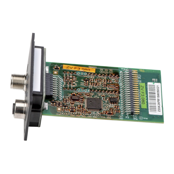
The GSD file can be read by a Profibus configuration tool, which is then used to configure the Profibus Master. The GSD file is a PROFIBUS DP standard text file, available for download from the KSB website. 1.3 Field bus module connections The field bus modules are plug-in modules. -
Page 5: Installing The Field Bus Module
1 Supplementary Operating Manual Table 2: Field bus module Component Description M12 connector A B-coded M12 socket B B-coded Amber LED signal lamp Device-internal bus communication OK (heartbeat detected) Green LED signal lamp Communication on field bus side active/possible Red LED signal lamp Profibus fault or communication error ▪... - Page 6 1 Supplementary Operating Manual Blind cover Fig. 2: Blind cover Blind cover 1. Unscrew the cross recessed head screws in the blind cover. 2. Remove the blind cover. Field bus module 1. Carefully insert the field bus module into the open slot. The plug-in module is guided on rails until it engages in the contact.
-
Page 7: Connecting The Field Bus Module
1 Supplementary Operating Manual 1.5 Connecting the field bus module For connecting the field bus module observe the installation guide of the Profibus user organisation (PNO) (download from "http://www.profibus.com/download/ installation-guide/"). Pay particular attention to the following: ▪ Before the bus connection is established among the nodes, potential equalisation must have been implemented and checked. - Page 8 1 Supplementary Operating Manual Fig. 6: Connecting a multiple pump system to the Profibus network (example) Profibus Master M12 cable for multiple pump configuration M12 cable for Profibus Further Profibus nodes Fig. 7: Pin assignment: a) Contact arrangement of M12 connector, b) Contact arrangement of M12 socket Table 4: Pin assignment Core colour code of Profibus cable...
-
Page 9: Setting The Parameters Of The Field Bus Module
1 Supplementary Operating Manual 1 2 3 4 5 1 2 3 4 5 1 2 3 4 5 1 2 3 4 5 Shielding Fig. 9: Wiring diagram Bus terminator The terminating resistors must conform to the following standard: Profibus standard DP DIN 19245, part 3, section 6.3. -
Page 10: Frequency Inverter Operation With Profibus Module
1 Supplementary Operating Manual Parameter Description Possible settings Factory setting 3-12-1-3 Cycle time, setpoint/control value 0.0...10.0 Time delay before the message (warning or alert) is triggered. In a redundant system, only a warning is output as the auxiliary master can assume the function. - Page 11 Parameter size in bytes Description Parameter description to PIP KSB menu number, Value range, Value (example) Mapping to functions by indicating the corresponding menu number (if available) and the valid value range for the parameters The operating values are indicated in the unit shown under Values. It corresponds with the four-digit number code to DIN IEC 61158 under VALUE_UNIT.
- Page 12 PhysicalBlock DIAGNOSIS_EXT_M OctetString 3 Diagnosis event in 0: No diagnosis event 00 00 00 ECHANICS the corresponding 1: Diagnosis event available component DIAGNOSIS_EXT_EL OctetString 3 00 00 00 ECTRICS DIAGNOSIS_EXT_P OctetString 2 00 00 ROC_LIQUID DIAGNOSIS_EXT_P 10 r OctetString 2 00 00 ROC_VACUUM DIAGNOSIS_EXT_O...
- Page 13 PumpActuation SETPOINT Float32 Setpoint (closed- 1-3-2, 0-100 % of the value range loop control) / 1-3-3 defined for the process variable Control value (open-loop control) SETPOINT_UNIT Unsigned16 2 1342 FEEDBACK Float32 Actual value 1-2-1, 0-100 % of the value range (closed-loop 1-2-3-1 defined for the process variable control) FEEDBACK_UNIT...
- Page 14 MultiPump PUMP_ROLE Unsigned8 Role in multiple 3-7-1 0: Slave (auxiliary control device) pump system 1: Master (active master control device) 2: Slave and auxiliary master (redundant master control device) OPERATION_MODE 3 Unsigned8 Single-pump/ 0: Stand alone mode (SPO) multiple-pump 3: Mixed redundancy and operating mode addition operation mode (MPO) NUMBER_OF_PUM...
- Page 15 PIDControl 14 rw TimeDiffere Rate time 3-6-4-4 0.00 100.00 ms 0 ms nce4 (differential constant) StandBy VALUE Boolean Status: operational FALSE: Not on stand-by TRUE availability TRUE: On stand-by PumpActivation VALUE Boolean Status: automatic 1-3-8 FALSE: Not in automatic mode TRUE mode TRUE: In automatic mode PumpOperation VALUE...
- Page 16 VolumeFlow VALUE_UNIT Unsigned16 2 1349 FlowVelocity VALUE Float32 Flow velocity of 1-2-3-8 fluid handled VALUE_UNIT Unsigned16 2 1061 Level VALUE Float32 Level 1-2-3-6 VALUE_UNIT Unsigned16 2 1010 Speed VALUE Float32 Speed 1-2-1-1 VALUE_UNIT Unsigned16 2 1085 Frequency VALUE Float32 Output frequency 1-2-1-7 VALUE_UNIT Unsigned16 2...
- Page 17 Energy VALUE Float32 Energy meter 1-4-1-1 (kWh) VALUE_UNIT Unsigned16 2 1179 OperationTime VALUE Float32 Pump operating 1-4-2-3 hours VALUE_UNIT Unsigned16 2 1059 TotalPoweredTime 31 VALUE Float32 Frequency inverter 1-4-2-1 1965 operating hours VALUE_UNIT Unsigned16 2 1059 Motor VOLTAGE Float32 Nominal motor 3-2-1-2 Motor name plate 0..480 V voltage...
- Page 18 13 r Float32 Maximum rated Name plate PumpDrive 2 current 20..120 A POWER_MAX 15 r Float32 Maximum rated Name plate PumpDrive 2 power 0..55 kW FREQUENCY_HIGH 17 r Float32 Maximum output 140 Hz: KSB SuPremE motor frequency 70 Hz: Other FREQUENCY_LOW 18 r Float32 Minimum output 0 Hz frequency...
-
Page 19: Definition Of The "Rotodynamic Pump" Module Available In The Cyclic Data Exchange
1 Supplementary Operating Manual 1.7.2 Definition of the "rotodynamic pump” module available in the cyclic data exchange The Rotodynamic Pump module serves to enter setpoints and control values for the pump set in a compact form. It also provides key information on the current operating status. - Page 20 1 Supplementary Operating Manual BYTE CB_CONTROL_MODE PumpActuation.CB_C 132: Differential pressure (sensorless) ONTROL_MODE 133: Flow rate 134: Flow rate (sensorless) 135: Temperature (cooling) 136: Temperature (heating) 137: Suction-side level 138: Discharge-side level BYTE CB_OPERATION_MOD PumpActuation.CB_O 128: Off PERATION_MODE (display: OFF) 129: Manual mode (display: MAN) 130: Automatic mode (display: AUTO)
-
Page 21: Definition Of The Feedback Module Available In The Cyclic Data Exchange
1 Supplementary Operating Manual Table 9: Rotodynamic Pump module, output BOOL PUMP_KICK_REQ PumpKick.VALUE 0 => 1 starts a functional check run BOOL REMOTE_OPERATION - Not supported BOOL DIRECTION_REQ Not supported BOOL RESET_FAULT GenericPump.RESET_ 0 => 1 acknowledges warnings and alerts and FAULT clears the fault BOOL... -
Page 22: Definition Of The Modules For Reading Out Process Values Available In The Cyclic Data Exchange
1 Supplementary Operating Manual 1.7.4 Definition of the modules for reading out process values available in the cyclic data exchange Each process value is represented by the corresponding module. All process values are of the REAL data type. Table 11: Process value modules, input Module designation Data type Description... - Page 23 1 Supplementary Operating Manual BOOL 0x901E DIA_AUX_DEVICE Auxiliary equipment diagnosis event BOOL 0x901F EXTENSION_AVAILA 1: Further error details are available in the extended diagnosis. Table 13: Module PB/DIAGNOSIS_EXT_HARDWARE (PhysicalBlock.DIAGNOSIS_EXT_HARDWARE), input BOOL 0x9101 HardwareFault 1: Hardware fault BOOL 0x9102 PowerSupply 1: Power supply fault BOOL 0x9103 DCLinkSupply...
- Page 24 1 Supplementary Operating Manual Table 16: Module PB/DIAGNOSIS_EXT_ELECTRICS (PhysicalBlock.DIAGNOSIS_EXT_ELECTRICS), input BOOL 0x9401 ElectricalFault Not supported BOOL 0x9402 InstallationFault Not supported BOOL 0x9403 SupplyVoltage Phase failure, mains side BOOL 0x9404 SupplyVoltHigh Overvoltage A2, W51 BOOL 0x9405 SupplyVoltLow Undervoltage A3, W52 BOOL 0x9406 SupplyCurrent Not supported BOOL...
- Page 25 1 Supplementary Operating Manual Table 18: PB/DIAGNOSIS_EXT_OPERATION (PhysicalBlock.DIAGNOSIS_EXT_OPERATION), input 0.0-3.0 BOOL 0x9701-0x9719 - Not supported BOOL 0x971A OverLoad Overload BOOL 0x971B PartialLoad Part load 3.3-4.0 BOOL 0x971C-0x9721 - Not supported BOOL 0x9722 DriveOverheat Heat sink temperature high A7, W59 BOOL 0x9723 MotorOverheat Thermal motor protection BOOL...
- Page 28 KSB SE & Co. KGaA Johann-Klein-Straße 9 • 67227 Frankenthal (Germany) Tel. +49 6233 86-0 www.ksb.com...
Need help?
Do you have a question about the Profibus PumpDrive 2 and is the answer not in the manual?
Questions and answers