Table of Contents
Advertisement
Quick Links
Instruction Manual
MIL 41000
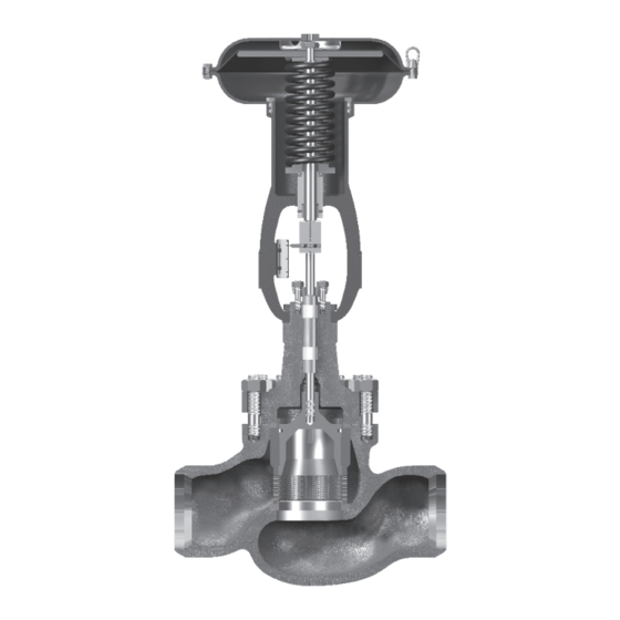
Heavy Duty Cage Guided Control Valves
Purchase Order No :
The following instructions should be thoroughly
reviewed and understood prior to installing, operating
or performing maintenance on this equipment.
Throughout the text, safety and/or caution notes will
appear and must be strictly adhered to, otherwise, serious injury
or equipment malfunction could result.
___________________________________________
Advertisement
Table of Contents

Related Manuals for KSB MIL 41000


Summary of Contents for KSB MIL 41000
- Page 1 Instruction Manual MIL 41000 Heavy Duty Cage Guided Control Valves Purchase Order No : ___________________________________________ The following instructions should be thoroughly reviewed and understood prior to installing, operating or performing maintenance on this equipment. Throughout the text, safety and/or caution notes will appear and must be strictly adhered to, otherwise, serious injury or equipment malfunction could result.
-
Page 2: Table Of Contents
TABLE OF CONTENTS Introduction......................3 General........................3 Unpacking .......................4 Installation ......................4 Air Piping .........................4 Valve Disassembly....................4 Body Disassembly....................4 Plug Disassembly.....................6 Maintenance & Repair.....................6 Packing Box......................6 Repair Of Seating Area....................8 Stroke Change......................8 Body Reassembly.....................8 Plug Stem Pinning....................9 Plug & Cage Assembly..................10 Note: Easily replaceable Pressure gauges for Air sets and externally mounted Pressure gauges of positioners are normally dismantled, separately packed and bound to the actuator yoke as a precaution against transit damages. -
Page 3: Introduction
2. General performing most of the maintenance required 41000 series heavy duty cage guided control on the MIL 41000 series control valves. valves are engineered for the most demanding Recommended spare parts required for applications in the industry, ranging from maintenance are listed in Parts List of page 12. -
Page 4: Unpacking
MIL Aftermarket department. Do not remove end protection cover before installation. 4. Installation Standard flow directions for MIL 41000 series Caution: Before installing the valve in the valves are as follows.However if the arrow line, clean piping and flush the line to... - Page 5 H. Remove plug (14) and cage (15) from body Guiding Surface (18) by pulling upward on the plug stem (1). (41400, 41500, 41600 & 41900 series valves). Then remove plug (14) from cage (15) by lifting cage over top of plug stem. In case of 411,412,413,417 series valves, the plug is removed by pulling the plug Guiding Surface...
-
Page 6: Plug Disassembly
Valve sizes 3" or 4" (80 or 100 mm) 6.2 Plug Disassembly Pressure must be applied on the pilot plug (21) A. Plug Stem Disassembly. to compress the pilot spring (22). The retaining ring (20) can now be removed, thus allowing (Model 41100,41200,41300,41500,41600,41700 removal of the pilot and spring from the valve plug. - Page 7 of the valve. If all compression is used up and Note: MIL Eco-lock packing (Figure 9) the valve leaks, then new packing is required. is a high performance system to keep fugitive emissions within allowable limits. The packing is provided with Caution: Valve must be isolated and the inner packing and outer packing the pressure vented before performing...
-
Page 8: Repair Of Seating Area
7.2 Repair of Seating Area Note: Intermittent lifting is important Any trim part which is scored or has damage on to keep the plug and seat concentric guiding surfaces, to the extent that the same during lapping. The lapping operation could interfere with proper valve action, should should be repeated four times before be replaced. -
Page 9: Body Reassembly
achieved using a new plug stem which is longer stroke. by the difference between existing and required The new stem can be ordered on our Aftermarket stroke. On the other hand, if the required stroke department. While ordering, do not forget to is more than existing valve stroke, same can be mention existing valve serial no. -
Page 10: Plug & Cage Assembly
After the plug has been pinned, it should upwards and then push down evenly be placed in a lathe to insure it is from all sides until the seal ring slips running “true.” The stem should be into the plug groove. placed in a collet with the plug shank Place cage into the body on the seat. - Page 11 Plug & Cage Assembly for 41600 series Caution: Care should be taken as the valves with PTFE Seal Ring graphite ring is fragile. This valve has inner elastomeric back up ring and outer PTFE ring. Insert the Slide the cage over the plug and stem back up ring into the plug groove.
- Page 12 TABLE 2: BOLTING TORQUE VALUES FOR 41104(Cv>10) SERIES VALVES SL NO Valve Size Rating * Stud Size (") No. of Studs Torque*(Nm) 2" <=600# 1/2-13 UNC-2A 2" 900#- 1500# 5/8-11 UNC-2A 2" 2500# 3/4-10 UNC-2A 3" 900#- 1500# 3/4-10 UNC-2A 3"...
- Page 13 TABLE 4: BOLTING TORQUE VALUES FOR 413/414/415/416/41900 SERIES VALVES SL NO Valve Size Rating * Stud Size(") No. of Studs Torque(Nm) 1.5" <=600# 5/8-11 UNC-2A 2" <=600# 3/4-10 UNC-2A 2" 900#-1500# 7/8 -9 UNC-2A 2" 2500# 1 -8 UNC-2A 2.5" 2500# 3/4 -10 UNC-2A 3"...
- Page 14 TABLE 4: BOLTING TORQUE VALUES FOR 413/414/415/416/41900 SERIES VALVES SL NO Valve Size Rating * Stud Size(") No. of Studs Torque(Nm) 10" 1500# 1 3/4-8 UNS-2A 1720 12" <=300# 1 1/2-8 UN-2A 12" 600# 1 1/2-8 UN-2A 12" 900# 1 1/2-8 UN-2A 1010 12"...
- Page 15 Figure 15 Evenly tighten body stud nuts (10) in the Caution: In case of Eco-lock packing sequence and to the torque shown in ensure that the sequence of rings are table on Figure 15. not changed. Slide guide bush (23) over top plug stem, dropping it to the bottom of the packing Insert packing follower (5), flange (4) box.
- Page 16 Pilot Spring Body Nut Guide Bush Body Gasket Plug Pin ^ Recommended Spare Parts MIL 41000 - Typical Designs MIL 41100 Unbalanced Construction MIL 71100 Unbalanced Construction (in Globe body) (in Angle body) MIL 41200 Unbalanced Construction MIL 41300 (>=6”)Balanced Construction...
- Page 17 MIL 41000 - Typical Multi-Stage Designs MIL 41004 Double Stage Lo-dB Trim MIL 41003 Lo-dB / Anti-cavitation Double Stage with Diffuser Seat Trim with Diffuser Seat MIL 41700 Single Stage High Capacity MIL 41600 Balanced Constructiuon Unbalanced Valves...
- Page 18 MIL 41000 - Installation Recommendations Best Next Best Next Best Avoid If Possible Avoid If Possible Fourth Position Fourth Position Third Position Ensure Proper Support If Mounted In Position 5. Avoid Positions 3 & 4 When Valve Is Exposed To Rain/freezing.
- Page 20 Damage, if any, noticed to valve body and bonnet also should be replaced or repaired. After the life-cycle, we recommend to dispose the parts as per your established procedures, through approved agencies only. KSB MIL Controls Limited Meladoor, Annamanada, Pin - 680741 Thrissur District, Kerala, India Tel.
Need help?
Do you have a question about the MIL 41000 and is the answer not in the manual?
Questions and answers