KSB PumpDrive 2 Supplementary Operating Manual
Field bus module, bacnet ms/tp gateway
Hide thumbs
Also See for PumpDrive 2:
- Installation & operating manual (213 pages) ,
- Supplementary operating manual (20 pages)
Advertisement
Advertisement

Related Manuals for KSB PumpDrive 2


Summary of Contents for KSB PumpDrive 2
- Page 1 Field Bus Module BACnet MS/TP Gateway PumpDrive 2 Supplementary Operating Manual...
- Page 2 All rights reserved. The contents provided herein must neither be distributed, copied, reproduced, edited or processed for any other purpose, nor otherwise transmitted, published or made available to a third party without the manufacturer's express written consent. Subject to technical modification without prior notice. © KSB SE & Co. KGaA, Frankenthal 05/06/2019...
-
Page 3: Table Of Contents
Contents Contents Supplementary Operating Manual ....................... 4 General................................ 4 Function ................................ 4 Field bus module connections ......................... 4 Installing the field bus module........................ 5 Connecting the field bus module ........................ 7 Setting the parameters of the field bus module .................... 9 Operation of frequency inverter with BACnet MS/TP.................. 11 BACnet MS/TP Gateway 3 of 16... -
Page 4: Supplementary Operating Manual
M12 connectors and terminating resistors), see the type series booklet. EDE lists KSB provides an EDE file on the KSB web site for exchanging PumpDrive-specific BACnet information. The EDE lists document all inbound and outbound objects with the associated defined properties. -
Page 5: Installing The Field Bus Module
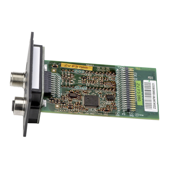
1 Supplementary Operating Manual Fig. 1: Field bus module Table 2: Field bus module Component Description M12 connector A B-coded, 5-pole M12 socket B B-coded, 5-pole Amber LED signal lamp Device-internal bus communication OK (heartbeat detected) Green LED signal lamp Communication: Valid data package received Red LED signal lamp Token loss (token timeout) ▪... - Page 6 1 Supplementary Operating Manual Blind cover Fig. 2: Blind cover Blind cover 1. Unscrew the cross recessed head screws in the blind cover. 2. Remove the blind cover. Field bus module 1. Carefully insert the field bus module into the open slot. The plug-in module is guided on rails until it engages in the contact.
-
Page 7: Connecting The Field Bus Module
1 Supplementary Operating Manual 1.5 Connecting the field bus module Observe the following when connecting the field bus module: ▪ Before the bus connection is established among the nodes, potential equalisation must have been implemented and checked. ▪ For high-frequency shielding, use shielded cables and assemble according to EMC requirements. - Page 8 1 Supplementary Operating Manual Fig. 6: Connecting a dual-pump system to the BACnet network (example) BACnet A device M12 cable for dual-pump configuration M12 cable, BACnet MS/TP Additional subscribers to BACnet Fig. 7: Pin assignment: a) Module contact arrangement b) Connector contact arrangement Table 4: Pin assignment Conductor colour...
-
Page 9: Setting The Parameters Of The Field Bus Module
1 Supplementary Operating Manual Shielding Fig. 8: User-configured cable Ⓜ M12 connector Ⓝ M12 connector 1 2 3 4 5 1 2 3 4 5 1 2 3 4 5 1 2 3 4 5 Shielding Fig. 9: Wiring diagram Bus terminator Bus system termination is implemented as follows in line with the BACnet standard: Fig. 10: Bus terminator Bus termination with polarisation is implemented at the start of the MS/TP bus in line with the BACnet standard (typically at the BACnet router). - Page 10 MSTP network for a longer period of time, a broken wire is reported. 3-12-5-6 Device Name Configuration via configuration KSB PumpDrive tool, maximum of 32 characters Device Object-Name Device name for device identification in the network 3-12-5-7 Device Description...
-
Page 11: Operation Of Frequency Inverter With Bacnet Ms/Tp
1.7 Operation of frequency inverter with BACnet MS/TP The frequency inverter fulfils device profile B-ASC as per BACnet standard ANSI/ASHREA135-2010. All BACnet characteristics required for the device type and interoperability range are fulfilled. Additional properties are also supported. All supported capabilities of the BACnet module are listed in the “Protocol Implementation Conformance Statement”... - Page 12 Object name Object type Unit/StateText table Description Value range Comment PD2-A-ControllerMode 19 (MV) 3-6-1 Type of Control 8 = Temperature The HMI has equivalent priority with (Heating) the field bus (the value written last is valid). 9 = Fill Level/Draining 10 = Fill Level/Filling 11 = Flow Rate (Sensorless) PD2-A-...
- Page 13 Table 7: Data sharing objects in frequency inverter: Pump parameters (PD2-#-…) Object name Object Unit/StateText table Description Value range Comment type PD2-#-PumpState 13 (MI) 1-7-10 PumpState 1 = Not Connected - 2 = Stopped 3 = Running 4 = Running Down 5 = Starting Up 6 = Disabled 7 = Disabled In Operation 8 = Idle Mode...
- Page 14 Object name Object Unit/StateText table Description Value range Comment type PD2-#-DiffPressure 0 (AI) BARS 1-2-2-3 Pump Differential - Pressure PD2-#-Flow 0 (AI) CUBIC-METERS-PER- 1-2-2-4 Pump Flow Rate - HOUR PD2-#-kWhCounter 0 (AI) KILOWATT-HOURS 1-4-1-1 Energy Meter (kWh) - PD2-#-OperatingTimeFC 0 (AI) HOURS 1-4-2-1 Frequency Inverter...
- Page 16 KSB SE & Co. KGaA Johann-Klein-Straße 9 • 67227 Frankenthal (Germany) Tel. +49 6233 86-0 www.ksb.com...
Need help?
Do you have a question about the PumpDrive 2 and is the answer not in the manual?
Questions and answers