Sign In
Upload
Manuals
Brands
KSB Manuals
DC Drives
PumpDrive 2 Eco
KSB PumpDrive 2 Eco Frequency Inverter Manuals
Manuals and User Guides for KSB PumpDrive 2 Eco Frequency Inverter. We have
4
KSB PumpDrive 2 Eco Frequency Inverter manuals available for free PDF download: Installation & Operating Manual, Application Manual, Supplementary Operating Manual
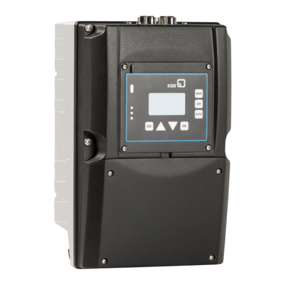
KSB PumpDrive 2 Eco Installation & Operating Manual (213 pages)
Self-cooling Motor-independent
Brand:
KSB
| Category:
DC Drives
| Size: 24 MB
Table of Contents
Table of Contents
3
Glossary
5
Key to Safety Symbols/Markings
6
General
6
Intended Use
6
Personnel Qualification and Training
7
Safety Awareness
7
Safety Information for the User/Operator
7
Consequences and Risks Caused by Non-Compliance with this Operating Manual
7
Safety Information for Maintenance, Inspection and Installation
7
Unauthorised Modes of Operation
8
Software Changes
8
Electromagnetic Compatibility (EMC)
8
Interference Emission Requirements
8
Line Harmonics Requirements
9
Interference Immunity Requirements
9
EMC Properties of the Frequency Inverter
9
2 Transport/Temporary Storage/Disposal
10
Checking the Condition Upon Delivery
10
Storage
11
Transporting a Vertical Pump Set
11
Transporting the Motor with Frequency Inverter
11
Transporting the Frequency Inverter with Lifting Gear
11
Disposal/Recycling
12
Ambient Conditions for Storage
12
Principles
13
Target Group
13
Symbols
13
3 General
13
Other Applicable Documents
13
4 Operation
14
Graphical Control Panel
14
Graphical Display
14
Assignment of Keys
15
Assignment of Keys for Manual Mode
16
Menu Keys
16
Menu Display
16
Menu: Operation
17
Access Levels
17
Access Level Parameters
17
Parameters for Changing Passwords
17
Menu: Diagnosis
18
Message Display
18
Acknowledging and Resetting Messages
18
Acknowledgement Types for Messages
19
Parameters for Display Language
19
Parameters for Setting the Control Panel
20
Operating Values on Main Screen
20
Menu: Information
21
Service Interface and LED Traffic Light Function
21
LED Description
22
5 Commissioning Report
23
General Description
24
Designation
24
Name Plate
26
Power Range and Sizes
26
Technical Data of Frequency Inverter
27
Technical Data of I/O Extension Board
28
Dimensions and Weights
30
Mounting Options
31
Motor Mounting
31
Wall Mounting
31
Cabinet Mounting
31
7 Installation at Site
32
Safety Regulations
32
Mounting Pumpdrive
32
Checks to be Carried out Prior to Installation
32
Motor Mounting
32
Wall/Control Cabinet Mounting
32
Electrical Connection
33
Minimum Distances for Control Cabinet Mounting
33
Safety Regulations
33
Information for Planning the System
34
Power/Connection Cables
34
Selecting the Power/Connection Cables
34
Cable Cross-Section, Control Terminals
35
Power/Connection Cable Properties
35
Electrical Protection Device
36
Information on Electromagnetic Compatibility
36
Length of Motor Connection Cable
36
Earth Connection
37
Line Chokes
37
C-Shaped Housing Cover
38
Electrical Connection
38
Output Filter
38
Removing the Housing Cover
38
Protective Cover
39
Prying Open the Protective Cover
39
Removing the Protective Cover
39
Establishing an Earth Connection
49
Installing and Connecting the M12 Module
49
M12 Module
50
Blind Cover
51
Connecting Dual and Multiple Pump Configurations
51
Inserting the M12 Module
51
Securing the M12 Module
51
Connecting M12 Modules in Dual and Multiple Pump Configurations
52
Connecting Pumpmeter in Single-Pump Configurations
52
Connecting the M12 Module to Pumpmeter in Single-Pump Configurations
52
Connecting Pumpmeter in Dual and Multiple Pump Configurations
53
Pin Assignment
53
Installing and Connecting the Field Bus Module
54
Installing the Field Bus Module
54
Field Bus Module
55
Inserting the Field Bus Module
55
Connecting the Field Bus Module
56
Installing and Connecting the I/O Extension Board
56
Connecting the Control Cable
57
Installing the I/O Extension Board
57
Structure of Electric Cable
57
Control Terminal
58
Control Terminal Assignment
59
Analog Inputs
60
Analog Outputs
60
Connecting Sensors to the Differential Analog Input
60
Relay Outputs
60
Control Terminal Assignment, I/O Extension Board
61
Changing the Installation Position of the Control Panel
62
Pin Assignment for M12 Connection Cable and Control Panel
63
8 Commissioning/Shutdown
64
Commissioning Wizard
64
Control Point Concept
65
Setting Motor Parameters
65
Motor Control Method
66
Parameters for Control Method
66
Parameters for Changing the V/F Characteristic
67
Automatic Motor Adaptation (AMA) of Frequency Inverter
67
Automatic Motor Adaptation (AMA) of Frequency Inverter for Asynchronous Motors
68
Parameters for Automatic Motor Adaptation for Asynchronous Motors
69
Automatic Motor Adaptation (AMA) of Frequency Inverter for KSB Supreme Motors
69
Entering the Setpoint
70
Specifying a Setpoint/Manual-Mode Control Value Via the Control Panel
70
Alternative Control Value and Setpoint
71
Pump Operation
72
Single-Pump Operation
72
Open-Loop Control Mode
72
Open-Loop Control Mode Using External Standard Signal
72
Example of Open-Loop Control Mode Using External Standard Signal
73
Open-Loop Control Mode Via Control Panel
73
Example of Open-Loop Control Mode Via Control Panel
74
Closed-Loop Control Mode
74
Overall Structure of the Process Controller
74
Selecting the Type of Control
74
Control Direction
75
Setting the Setpoint or Control Value
75
Setting the Actual Value
75
Setting the Process Controller
75
Parameters of the PID Controller
76
Automatic Determination of Controller Parameters
76
Closed-Loop Control Mode Via Control Panel
77
Terminal Wiring Diagram, Closed-Loop Control Mode
78
Closed-Loop Control Mode with External Setpoint Signal
79
Sensorless Differential Pressure Control
80
Sensorless Flow Rate Control
81
Parameters for Sensorless Differential Pressure Control
81
Multiple Pump Configuration
82
Multiple Pump Configuration in Closed-Loop Control Mode
82
Parameters for Sensorless Flow Rate Estimation
82
Switching Limits of a Running Pump in a Multiple Pump System
85
Start Speed
85
Start Flow Rate
85
Low Flow Limit
85
Switching Limits of Two Running Pumps in a Multiple Pump System
86
Automatic Pump Changeover
87
Application Functions
87
Aligning the Frequency Inverter with the Pump
87
Flow Rate Estimation
87
Power Curve with Seven Data Points and the Relevant Parameters
88
Parameters for Matching Pumpdrive to the Pump
88
Protective Functions
89
Activating/Deactivating Thermal Motor Protection
89
Electrical Motor Protection by Overvoltage/Undervoltage Monitoring
90
Stop Due to Overcurrent
90
Dynamic Overload Protection by Speed Limitation
90
Tripping at Phase Failure and Short Circuit
91
Broken Wire Detection (Live Zero)
91
Suppressing a Frequency Range
92
Suppressing a Frequency Range in Closed-Loop Control Mode
92
Suppressing a Frequency Range in Open-Loop Control Mode
92
Dry Running Protection and Protection against Hydraulic Blockage
92
Operating Point Monitoring
93
Functional Check Run
94
Head / Flow Rate Diagram
94
Operating Point Monitoring Parameters
94
Functional Check Run after Idle Period
94
Parameters for Functional Check Run after Idle Period
95
Parameters for Functional Check Run after Idle Period at Defined Time
95
Starting the Functional Check Run Via the Control Panel
95
Individual Monitoring Functions
96
Service Interval
96
Flow Rate Estimation
96
Multiple Pump Systems
97
Improving Accuracy with Pressure Sensors Installed Close to the Pump
97
Flow Rate Estimation Parameters
97
Energy Optimisation
98
Open Piping System
98
Pressure Control with Dynamic Pressure Compensation in Open System
98
Closed Piping System
99
Based on Flow Rate
99
Sleep Mode
103
Sleep Mode with Setpoint Increase
104
Restarting
104
Sleep Mode Without Setpoint Increase
105
Energy Savings Meter
105
Parameters for Stand-By (Sleep) Mode
105
Constant Reference Power
106
Energy Savings with Constant Reference Power
106
Variable Reference Power
107
Energy Savings with Variable Reference Power
107
Energy Savings Meter Parameters
107
Waste Water Function
108
Starting the Pump Set at Maximum Speed
108
Monitoring Minimum Flow Velocity and Pipe Flushing
108
Pipe Flushing
109
Ramps
109
Operating Ramp (Open-Loop Control Mode/Manual Mode)
110
Start and Stop Ramp Parameters
110
Operating Ramp Parameters
111
Setpoint Ramp (Closed-Loop Control Mode)
111
Device Functions
112
Motor Standstill Heater
112
Factory and User Settings
112
Motor Standstill Heater Parameters
112
Read out Pumpmeter
113
Digital and Analog Inputs/Digital and Analog Outputs
114
Date and Time
114
List of Parameters with Preassignment of Function
115
External Message
116
Digital Potentiometer Parameters
116
Fixed-Speed Operation
117
External Message Parameters
117
Wiring of Digital Inputs
117
Parameters for Fixed Speed Operation Via Digital Inputs
117
Starting the Functional Check Run Via Digital Input
118
Analog Inputs
118
Relay Outputs
120
Analog Outputs
122
Inputs and Outputs of the I/O Extension Board
123
Parameterising the M12 Module
127
Pumpmeter Connection Via Modbus
128
Parameterising the Field Bus Module
130
Modbus RTU Module Parameters
131
Profibus Module Parameters
132
LON Module Parameters
132
9 Servicing/Maintenance
133
Supervision of Operation
133
Safety Regulations
133
Preparing Frequency Inverter for Dismantling
134
10 Parameter List
135
Selection Lists
188
11 Trouble-Shooting
189
Faults/Malfunctions
189
Alerts
190
Warnings
193
Information Messages
195
12 Purchase Order Specifications
196
Ordering Spare Parts
196
Accessories
197
Service Software
197
Control Panels
197
Motor Adapter Kits
197
Adapter for Wall and Cabinet Mounting
199
M12 Module
199
Installation Options
200
Sensor System
202
Accessories: Pressure Measurement
202
S-11 Pressure Transducer
203
Control Cabinet Mounting
205
Accessories: Potential Separator
205
Accessories – Filters
205
13 EU Declaration of Conformity
207
Index
208
Advertisement
KSB PumpDrive 2 Eco Installation & Operating Manual (172 pages)
Self-cooling, motor-independent frequency inverter
Brand:
KSB
| Category:
DC Drives
| Size: 22 MB
Table of Contents
Table of Contents
3
Glossary
5
1 General
6
Principles
6
Target Group
6
Other Applicable Documents
6
Symbols
6
2 Safety
7
Key to Safety Symbols/Markings
7
General
7
Intended Use
7
Personnel Qualification and Training
8
Consequences and Risks Caused by Non-Compliance with this Operating Manual
8
Safety Awareness
8
Safety Information for the User/Operator
8
Safety Information for Maintenance, Inspection and Installation
8
Unauthorised Modes of Operation
9
Software Changes
9
Electromagnetic Compatibility (EMC)
9
Interference Emission Requirements
9
Line Harmonics Requirements
10
Interference Immunity Requirements
10
3 Transport/Temporary Storage/Disposal
11
Checking the Condition Upon Delivery
11
Transport
11
Storage
12
Disposal/Recycling
13
4 Description
14
General Description
14
Designation
14
Name Plate
16
Power Range and Sizes
16
Technical Data
17
Dimensions and Weights
19
Mounting Options
20
5 Installation at Site
21
Safety Regulations
21
Checks to be Carried out Prior to Installation
21
Mounting Pumpdrive
21
Motor Mounting
21
Wall/Control Cabinet Mounting
21
Electrical Connection
22
Safety Regulations
22
Information for Planning the System
23
Electrical Connection
27
6 Operation
45
Standard Control Panel
45
Display
45
Main Screen
48
Settings Menu
49
Service Interface and LED Traffic Light Function
52
7 Commissioning/Shutdown
53
Control Point Concept
53
Setting Motor Parameters
53
Motor Control Method
54
Automatic Motor Adaptation (AMA) of Frequency Inverter
56
Automatic Motor Adaptation (AMA) of Frequency Inverter for Asynchronous Motors
56
Automatic Motor Adaptation (AMA) of Frequency Inverter for KSB Supreme Motors
57
Entering the Setpoint
58
Pump Operation
59
Single-Pump Operation
59
Multiple Pump Configuration
72
Application Functions
78
Aligning the Frequency Inverter with the Pump
78
Flow Rate Estimation
78
Protective Functions
80
Energy Optimisation
87
Ramps
94
Motor Standstill Heater
97
Device Functions
98
Factory and User Settings
98
Reading out Pumpmeter
98
Date and Time
99
Digital and Analog Inputs/Digital and Analog Outputs
100
Digital Inputs
100
Analog Inputs
104
Relay Output
107
Analog Outputs
108
Parameterising the M12 Module
109
Parameterising the Field Bus Module
112
8 Servicing/Maintenance
114
Safety Regulations
114
Servicing/Inspection
114
Supervision of Operation
114
Dismantling
115
Preparing Frequency Inverter for Dismantling
115
9 Parameter List
116
Selection Lists
144
10 Trouble-Shooting
145
Faults/Malfunctions: Trouble-Shooting
145
Alerts
146
Warnings
149
Information Messages
151
11 Purchase Order Specifications
152
Ordering Spare Parts
152
Accessories
153
Service Software
153
Motor Adapter Kits
153
Adapter for Wall / Cabinet Mounting
157
M12 Module
157
Optional Components
159
Sensor System
160
Control Cabinet Mounting
164
12 Commissioning Report
166
13 EU Declaration of Conformity
167
Index
168
KSB PumpDrive 2 Eco Application Manual (50 pages)
Self-cooling Motor-independent Frequency Inverter
Brand:
KSB
| Category:
DC Drives
| Size: 2 MB
Table of Contents
Table of Contents
3
1 Pre-Conditions
4
Pump Characteristc Curve
7
Parameterization of Motor Data
8
2 Single Pump
9
Single Pump - Open Loop Control
9
Open Loop Control: Control Value at Display
9
Open Loop Control: Control Value by External Signal 0
10
Open Loop Control: Control Value by External Signal 4
11
Open Loop Control: Digital Motor Potentiometer
12
Single Pump - Closed Loop Control
13
Closed Loop Control: Differential Pressure with Pumpmeter (Modbus)
13
Closed Loop Control: Differential Pressure with Sensor 4
14
Closed Loop Control: Differential Pressure with Sensor 4
15
Closed Loop Control: Differential Pressure with 2 Pressure Sensors 4
16
Closed Loop Control: Sensorless Differential Pressure Control
17
Closed Loop Control: Pressure with Pressure Sensor 4
18
Closed Loop Control: Pressure with Pumpmeter (Modbus)
19
Closed Loop Control: Pressure with Pressure Sensor 0
20
Closed Loop Control: Pressure, Set Point (Closed Loop) at Analog Input 0
21
Closed Loop Control: Constant Level at Low Pressure Side with Submersible Sensor 4
22
Closed Loop Control: Temperature with Thermometer 4
23
Closed Loop Control: Flow Rate with Flow Rate Sensor 4
24
3 Double Pump
25
Double Pump - Open Loop Control
25
Open Loop Control: Control Value at Display
25
Open Loop Control: Control Value with External Signal
27
Double Pump - Closed Loop Control
29
Closed Loop Control Non Redundant: Differential Pressure with Pumpmeter (Modbus) - Typical Application
29
Closed Loop Control Redundant: Differential Pressure with Pumpmeter (Modbus)
31
Closed Loop Control Redundant: Discharge Pressure with Sensor 4
33
Closed Loop Control Redundant: Discharge Pressure with Pressure Sensor 4
36
4 Pump Functionality
39
Closed Loop Control
39
Closed Loop Control: Dynamic Differential Pressure Set Point Compensation Based on Flow Rate Estimation
39
Closed Loop Control: Dynamic Differential Pressure Set Point Compensation Based on Speed
41
Open Loop Control: 1 Fix Speed Selected by Digital Switches or Variable Speed Via Analog Signal
42
Closed Loop Control: Sleep Mode
43
5 M12 Cable
44
Bus Cable for Connecting Pumpmeter to the M12-Module
44
Bus Cable for Double- and Multi Pump Operation
45
Crosslink Cable
46
M12 Cable for Fieldbus Module Modbus RTU
47
6 Project
48
7 Other Documents
49
Advertisement
KSB PumpDrive 2 Eco Supplementary Operating Manual (20 pages)
Modbus RTU Module
Brand:
KSB
| Category:
Control Unit
| Size: 2 MB
Table of Contents
Table of Contents
3
Supplementary Operating Manual
4
General
4
Field Bus Module Connections
4
Installing the Field Bus Module
4
Connecting the Field Bus Module
6
Modbus RTU Module
6
Modbus RTU Protocol
9
Advertisement
Related Products
KSB PumpDrive 2
KSB PumpDrive
KSB Amaprop 2500
KSB CORA 2C
KSB CORA 2AH
KSB 202152
KSB MEGAFLOW 200-315
KSB MEGAFLOW 200-500
KSB MEGAFLOW 250-500
KSB Rotex 20/100E
KSB Categories
Water Pump
Control Unit
Industrial Equipment
Extender
Controller
More KSB Manuals
Login
Sign In
OR
Sign in with Facebook
Sign in with Google
Upload manual
Upload from disk
Upload from URL