Table of Contents
Advertisement
Quick Links
Advertisement
Table of Contents

Related Manuals for KSB Cervomatic EDP.2


Summary of Contents for KSB Cervomatic EDP.2
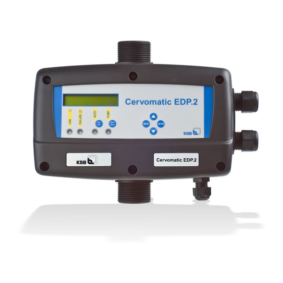
- Page 1 Automatic Control Unit Cervomatic EDP.2 Installation/Operating Manual...
- Page 2 All rights reserved. The contents provided herein must neither be distributed, copied, reproduced, edited or processed for any other purpose, nor otherwise transmitted, published or made available to a third party without the manufacturer's express written consent. Subject to technical modification without prior notice. © KSB SE & Co. KGaA, Frankenthal 09/01/2018...
-
Page 3: Table Of Contents
Configuration............................. 16 6.2.3 Pre-charging of accumulator...................... 18 Shutdown/storage/preservation ........................ 18 Returning to service ............................ 18 Maintenance............................ 19 Trouble-shooting.......................... 20 Related Documents .......................... 22 Wiring diagrams ............................. 22 Additional electrical connections ........................ 23 EU Declaration of Conformity ...................... 24 Index .............................. 25 Cervomatic EDP.2 3 of 28... -
Page 4: General
The serial number uniquely describes the system and is used as identification in all further business processes. In the event of damage, immediately contact your nearest KSB service centre to maintain the right to claim under warranty. 1.2 Target group This operating manual is aimed at the target group of trained and qualified specialist technical personnel. -
Page 5: Safety
The values specified in the technical product literature for the mains voltage, mains frequency, ambient temperature, and motor current must not be exceeded. The automatic control unit must only be operated in accordance with the instructions provided in the operating manual and other applicable documents (ð Section 1.3, Page 4) . Cervomatic EDP.2 5 of 28... -
Page 6: Personnel Qualification And Personnel Training
In addition to the safety information contained in this manual and the intended use, the following safety regulations shall be complied with: ▪ Accident prevention, health and safety regulations ▪ Explosion protection regulations ▪ Safety regulations for handling hazardous substances ▪ Applicable standards, directives and laws Cervomatic EDP.2 6 of 28... -
Page 7: Transport/Temporary Storage/Disposal
1. On transfer of goods, check each packaging unit for damage. 2. In the event of in-transit damage, assess the exact damage, document it and notify KSB or the supplying dealer (as applicable) and the insurer about the damage in writing immediately. -
Page 8: Disposal
3.4 Disposal NOTE Due to certain components it contains, the device is classified as special waste and meets RoHs 2011/65/EC requirements. Once decommissioned, the device must be properly disposed of in accordance with local regulations. Cervomatic EDP.2 8 of 28... -
Page 9: Description
P max: 1000 kPa- 10 bar Ip55 Freq. 50/60 Hz Imax 16(10) A V: 1~230 Pump: 1~230 V: 3~230 Pump: 3~230 V: 3~400 Pump: 3~400 KSB SE & Co. KGaA Johann-Klein-Straße 9 67227 Frankenthal Deutschland Fig. 1: Name plate (example) Product code Serial number, firmware version V1.11, 05 not relevant, month of... -
Page 10: Design Details
Ambient temperature 0 - +50 °C Maximum flow rate 15 m Minimum flow rate 0.09 m Maximum start pressure 6.5 bar (pressure-dependent mode) Maximum stop pressure 7 bar (pressure-dependent mode) Range of start pressure (on/off 1 - 5 bar mode) Cervomatic EDP.2 10 of 28... -
Page 11: Displays And Indicator Lamps
4 Description 4.7 Displays and indicator lamps Cervomatic EDP.2 MENU Fig. 2: Indicator lamps Display of various parameters during configuration. In operation, the current pressure, configured start-up pressure and alerts are displayed. AUTO On/Off button: For selecting between manual and automatic mode. -
Page 12: Installation At Site
The automatic control unit has an integrated accumulator. An external accumulator is not required. For frequent water extraction, it is recommended that the system be used in dedicated pressure-dependent mode and an external accumulator be installed. Cervomatic EDP.2 12 of 28... -
Page 13: Connecting The Piping
▪ The pump has an integrated vent valve. For submersible borehole pumps, the automatic venting function facilitates priming under back pressure. CAUTION Plastic threaded connections sealed with hemp Stresses/strains and leaks in the plastic piping! ▷ Use Teflon tape for sealing. Cervomatic EDP.2 13 of 28... -
Page 14: Electrical Connection
Connection procedure (ð Section 9.2, Page 23) ▪ Level switch of inlet tank: (e.g. via float switch in inlet tank) Input for stopping pump as soon as the external switch for detecting the minimum fill level trips. Connection procedure (ð Section 9.2, Page 23) Cervomatic EDP.2 14 of 28... - Page 15 When closing the housing after establishing the electrical connection, ensure that the housing gasket is correctly seated. Ensure that the internally routed wires do not get trapped. Check the pump's direction of rotation during commissioning. Cervomatic EDP.2 15 of 28...
-
Page 16: Commissioning/Start-Up/Shutdown
Press the ▲ ▼ buttons to change the values and ENTER to save them. Press MENU to exit the configuration procedure. Every time the ENTER button is pressed, the different displays are shown with the individual configuration steps. Cervomatic EDP.2 16 of 28... - Page 17 PLINE MENU MENU 03,0 bar 02,0 bar 3” The message that is briefly displayed provides information on the 3” Cervomatic EDP.2 ENTER V 0.0 software version. Use the ▲ ▼ buttons to select the respective language: "SPRACHE LANGUAGE MENU ENTER ENGLISH DEUTSCH", "LANGUAGE ENGLISH", "LANGUE FRANÇAISE", "LINGUA...
-
Page 18: Pre-Charging Of Accumulator
▪ Leave the automatic control unit to dry and store in a dry, dark and frost-proof room. ▪ Special preservation measures are not required. 6.4 Returning to service For returning the equipment to service, observe the items on commissioning/start-up. Cervomatic EDP.2 18 of 28... -
Page 19: Maintenance
7 Maintenance 7 Maintenance Check the proper functioning of the automatic control unit once per year. Cervomatic EDP.2 19 of 28... -
Page 20: Trouble-Shooting
If problems occur that are not described in the following table, consultation with the KSB customer service is required. A1 Lack of water A2 Fill level sensor... - Page 21 (ð Section 6.2.3, Page 18) This occurs only in pressure-dependent mode. None No display Check the electrical connection and power supply. Call in customer service. No longer available from 2014 production date Cervomatic EDP.2 21 of 28...
-
Page 22: Related Documents
3~400 V 3~230 V 1~230 V Fig. 4: Wiring diagram of automatic control unit to pump Connection to power supply 3~400 V 3~230 V 1~230 V Fig. 5: Wiring diagram of automatic control unit to power supply Cervomatic EDP.2 22 of 28... -
Page 23: Additional Electrical Connections
9 Related Documents 9.2 Additional electrical connections MAX. MIN. Fig. 6: Additional electrical connections General fault message relay Input for inlet tank monitoring Cable entry Fig. 7: Cable entry in housing Pump Power supply Inlet tank monitoring (optional) Cervomatic EDP.2 23 of 28... -
Page 24: Eu Declaration Of Conformity
10 EU Declaration of Conformity 10 EU Declaration of Conformity KSB SE & Co. KGaA Manufacturer: Johann-Klein-Straße 9 67227 Frankenthal (Germany) The manufacturer herewith declares that the product: Cervomatic EDP.2 Series code range: 2016w16 to 2018w52 ▪ is in conformity with the provisions of the following Directives as amended from time to time: –... -
Page 25: Index
Index Index Commissioning/start-up 16 Design 10 Designation 9 Disposal 8 Faults Causes and remedies 20 Name plate 9 Other applicable documents 4 Safety 5 Safety awareness 6 Storage 7 Transport 7 Cervomatic EDP.2 25 of 28... - Page 28 KSB SE & Co. KGaA Johann-Klein-Straße 9 • 67227 Frankenthal (Germany) Tel. +49 6233 86-0 www.ksb.com...
Need help?
Do you have a question about the Cervomatic EDP.2 and is the answer not in the manual?
Questions and answers