Advertisement
Quick Links
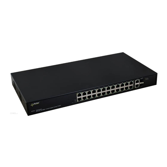
Switch 24 ports
24 PoE ports 10/100 Mb/s (data transfer and power supply)
2 ports 10/100/1000 Mb/s (G1/TP, G2/TP ports) (UpLink)
2 ports 10/100/1000 Mb/s SFP (G1/SFP, G2/SFP ports)
(UpLink)
30 W for each PoE port, supports devices complaint with
IEEE802.3 af/at (PoE+) standard
the
Supports auto-learning and auto-aging of MAC addresses
(16 K size)
1. Technical description.
1.1. General description.
SF124 is a 24-ports PoE switch designed to supply IP cameras operating in IEEE 802.3af/at standard.
Automatic detection of any devices powered in the PoE/PoE+ standard is enabled at the 1 – 8 ports of the switch. The G1/TP
and G2/TP ports is used for connection of another network device via RJ45 connector. The switch is fitted with SFP slots
(marked as G1/SFP and G2/SFP), the use of fiber optic module (GBIC) allows fiber optic transmission. The operating status of
the device (described in the table below) is displayed on the LED display on the front panel.
The PoE technology ensures a network connection and reduces installation costs by eliminating the need to supply a
separate power cable for each device. This method allows supplying other network devices, such as IP phone, wireless access
point or router.
SF124
v1.1
SF124 24-ports switch for 24 IP cameras
Edition: 2 from 14.02.2019
Supercedes the edition: 1 from 06.06.2018
Features
:
Example of use.
1
LED indication
Additional assembly elements
warranty – 2 year from the production
date
EN
Advertisement

Related Manuals for Pulsar SF124


Summary of Contents for Pulsar SF124
- Page 1 1.1. General description. SF124 is a 24-ports PoE switch designed to supply IP cameras operating in IEEE 802.3af/at standard. Automatic detection of any devices powered in the PoE/PoE+ standard is enabled at the 1 – 8 ports of the switch. The G1/TP and G2/TP ports is used for connection of another network device via RJ45 connector.
- Page 2 1.2. Block diagram. Fig. 1. Block diagram. 1.3. Description of components and connectors. Table 1. (see Fig. 2, 3 and 4) Element no. Description (Fig . 2) LED indication 24 x PoE port (1÷24) 2 x UPLINK ports (G1/TP, G2/TP) 2 x UPLINK ports (G1/SFP, G2/SFP) Power Socket of the AC Additional mounting elements...
- Page 3 Fig. 4. The view switch'a. 1.4. Technical parameters Table 2. 24 x PoE (10/100 Mb/s) (RJ-45) 2 x UpLink (10/100/1000 Mb/s) (RJ-45) Ports 2 x UpLink (10/100/1000 Mb/s) (SFP) with connection speed auto-negotiation and MDI/MDIX Auto Cross) PoE power supply IEEE 802.3af/at (1÷24 ports), 52 V DC / 30 W at each port * Protocols, Standards IEEE802.3, 802.3u, 802.3x CSMA/CD, TCP/IP...
- Page 4 2. Installation. 2.1. Requirements. The unit should be mounted in confined spaces, in accordance with the 2nd environmental class, with normal relative humidity (RH=90 % maximum, without condensation) and temperature from -10 °C to +40 °C. Ensure the free flow of air around the unit. The PSU shall work in a vertical position that guarantees sufficient convectional air-flow through ventilating holes of the enclosure.
-
Page 5: Weee Label
Waste electrical and electronic equipment must not be disposed of with normal household waste. According to the European Union WEEE Directive, waste electrical and electronic equipment should be disposed of separately from normal household waste. Pulsar sp. j. Siedlec 150, 32-744 Łapczyca, Poland Tel. (+48) 14-610-19-40, Fax. (+48) 14-610-19-50 e-mail: biuro@pulsar.pl,...
Need help?
Do you have a question about the SF124 and is the answer not in the manual?
Questions and answers