Advertisement
Quick Links
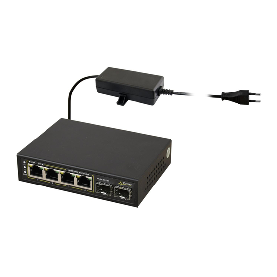
Switch 6 ports
4 PoE ports 10/100/1000 Mb/s
(data transfer and power supply)
2 ports 1000 Mb/s (UP LINK)
30 W for each PoE port, supports devices complaint
with the IEEE802.3af/at (PoE+) standard
Supports auto-learning and auto-aging of MAC
addresses (2K size)
1. Technical description
1.1. General description.
SFG64 is a 6-ports PoE switch designed to supply IP cameras operating in IEEE 802.3af/at standard. Automatic
detection of any devices powered in the PoE/PoE+ standard is enabled at the 1 – 4 ports of the switch. The UP LINK (G1 and
G2) ports is used for connection of another network device via of fiber optic (shall be used GBIC). The LEDs at the front panel
indicate the operation status (description in the table below).
The PoE technology ensures a network connection and reduces installation costs by eliminating the need to supply a
separate power cable for each device. This method allows supplying other network devices, such as IP phone, wireless access
point or router.
SFG64
v1.0
SFG64 6-port PoE switch for 4 IP cameras
Edition: 2 from 14.07.2022
Supercedes edition: 1 from 22.10.2019
Features:
PSD 520115 52 V DC/1,15 A/60 W max.
power supply desktop type included
Additional assembly elements
LED indication
warranty – 2 years from production date
Example of use.
1
PL
EN**
Advertisement

Subscribe to Our Youtube Channel
Related Manuals for Pulsar SFG64


Summary of Contents for Pulsar SFG64
- Page 1 1.1. General description. SFG64 is a 6-ports PoE switch designed to supply IP cameras operating in IEEE 802.3af/at standard. Automatic detection of any devices powered in the PoE/PoE+ standard is enabled at the 1 – 4 ports of the switch. The UP LINK (G1 and G2) ports is used for connection of another network device via of fiber optic (shall be used GBIC).
- Page 2 1.2 Block diagram. Fig. 1. Block diagram. 1.3. Description of components and connectors. Table 1. (see Fig.2) Element no. Description (Fig. 2) 2 x UP LINK port 4 x PoE port (1÷4) Power Socket of the DC Additional mounting elements Fig.
- Page 3 1.4. Technical parameters. Table 2. 6 ports (4 x PoE + 2 x UP LINK) 4 ports PoE 10/100/1000 Mb/s (RJ45) Ports 2 ports 1000 Mb/s (SFP) with connection speed auto-negotiation and MDI/MDIX Auto Cross PoE power supply IEEE 802.3af/at (1÷4 ports), 52 V DC / 30 W at each port * Protocols, Standards IEEE802.3, 802.3u, 802.3x CSMA/CD, TCP/IP Bandwidth...
- Page 4 Connection schemes:...
- Page 5 Waste electrical and electronic equipment must not be disposed of with normal household waste. According to the European Union WEEE Directive, waste electrical and electronic equipment should be disposed of separately from normal household waste. Pulsar sp. j. Siedlec 150, 32-744 Łapczyca, Poland Tel. (+48) 14-610-19-45 e-mail: sales@pulsar.pl...
Need help?
Do you have a question about the SFG64 and is the answer not in the manual?
Questions and answers