Table of Contents
Advertisement
Quick Links
Advertisement
Table of Contents

Subscribe to Our Youtube Channel
Related Manuals for Advantech MIC-6311


Summary of Contents for Advantech MIC-6311
- Page 1 User Manual MIC-6311 OpenVPX CPU Blade with Intel® 4th Core™ Processor...
- Page 2 No part of this manual may be reproduced, copied, translated or transmitted in any form or by any means without the prior written permission of Advantech Co., Ltd. Information provided in this manual is intended to be accurate and reliable. How- ever, Advantech Co., Ltd.
- Page 3 Class I, Division 2, Groups A, B, C and D indoor hazards. Technical Support and Assistance Visit the Advantech website at http://support.advantech.com to obtain the latest information about this product. Contact your distributor, sales representative, or Advantech's customer service center for technical support should you require additional assistance.
- Page 4 Before setting up the system, check that the items listed below are included and in good condition. If any item does not accord with the list, please contact your dealer immediately. MIC-6311 all-in-one single board computer (CPU heatsink and PCH heatsink included) x 1 Daughter board for SATA HDD x 1 (assembled) ...
- Page 5 The sound pressure level at the operator's position according to IEC 704-1:1982 is no more than 70 dB (A). DISCLAIMER: These instructions are provided according to IEC 704-1. Advantech disclaims all responsibility for the accuracy of any statements contained herein.
- Page 6 We Appreciate Your Input Please let us know whether any aspect of this product, including the manual, can benefit from improvements or corrections. We appreciate your valuable input in help- ing improve our products. MIC-6311 User Manual...
-
Page 7: Table Of Contents
Table 1.7: SW3 Front COM and RTM COM1/COM2 Port Selec- tion for BMC/SIO UART..........10 Connector Definitions................10 Table 1.8: MIC-6311 connector descriptions......10 Figure 1.4 MIC-6311 front panel ports, indicators and buttons.. 11 Table 1.9: Front Panel LEDs ............. 11 1.6.1 USB Connectors ................. 11 1.6.2... - Page 8 Installation....................13 1.8.1 HDD Installation................13 Figure 1.5 Complete assembly of MIC-6311 with SATA HDD .. 13 Figure 1.6 Fastening screws to the SATA HDD bracket ... 14 Figure 1.7 Inserting the SATA HDD into the SATA connector .. 14 1.8.2...
- Page 9 Activate FPGA Configuration ............61 BIOS Upgrade..................62 4.4.1 Load New BIOS Image ............... 62 4.4.2 Activate BIOS Image..............62 Verify Successful Upgrades ..............62 Appendix A Pin Assignments .......65 P0 Connector ..................66 Table A.1: P0 VPX I/O ............... 66 MIC-6311 User Manual...
- Page 10 Standard IPMI Commands (v2.0) ............94 Table G.1: IPM Device “Global” Commands......94 Table G.2: BMC Watchdog Timer Commands......94 Table G.3: BMC Device and Messaging Commands....94 Table G.4: Chassis Device Commands ........95 Table G.5: Event Commands............. 96 MIC-6311 User Manual...
- Page 11 PICMG IPMI Commands............... 101 Table G.19:AdvancedTCA (PICMG 3.0 R3.0 AdvancedTCA Base Specification) ............101 Table G.20:HPM.1 (R1.0) ............102 OEM/Group IPMI Commands ............... 102 Table G.21:Advantech OEM Commands........102 Appendix H Driver & Tools ........103 OpenIPMI ....................104 IPMITool....................104...
- Page 12 MIC-6311 User Manual...
-
Page 13: Chapter 1 Hardware Configuration
Chapter Hardware Configuration This chapter describes how to configure the MIC-6311 hardware. -
Page 14: Introduction
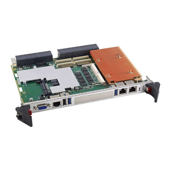
Introduction Advantech’s MIC-6311 is a single processor VPX blade based on an Intel 4th gener- ation Core i3/i5/i7 platform. The MIC-6311 enables the highest possible performance in the 6U VPX form factor with two SRIOx4 ports on the VPX data plane and two PCI Express x8 2nd generation lanes in the VPX expansion plane for workstation and computation-intensive applications. -
Page 15: Specifications
Two lanes of SRIO Gen2 x4, which offer 5G baud rates, are provided in the P1 data plane. The MIC-6311 uses two lanes of PCIe Gen2 x8 in the P2 expansion plane. Two lanes of 1GBase-T or SERDES (on request) are used for the P4 control plane. -
Page 16: Memory
RS232 / RS485 / RS422 modes using the onboard switch. 1.2.10 USB Ports Two USB 3.0-compliant ports with fuse protection are provided. Both ports are routed to the front panel connectors on the MIC-6311 and to the rear I/O module via a P5 connector. 1.2.11 LEDs Four LEDs are provided on the front panel as follows: ... -
Page 17: Mechanical And Environmental Specifications
When configured as a sys- tem controller, the bridge acts as a standard transparent PCI Express to PCI/PCI-X Bridge. The MIC-6311 receives power from the backplane and supports a rear I/O. The PLX PEX 8733 offers the following features: ... -
Page 18: Pmc (Pci Mezzanine Card) Ieee1386.1 Compliant
Additional I/O or co-processing functionality is supported by add-on PMC modules. The MIC-6311 supports one PMC site that is fully compliant with the VITA 46.9 PMC/ XMC Rear I/O Fabric Signal Mapping on 3U and 6U VPX Modules Standard specifi- cation. -
Page 19: Functional Block Diagram
SATAIII, 6GB/s for 2.5” User + Reset Handle SW SSD/ SATA buttons User LEDs Figure 1.1 MIC-6311 functional block diagram Board Map The figure below shows the location of the main components, jumpers, switches and thermal sensors. MIC-6311 User Manual... -
Page 20: Jumpers And Switches
Figure 1.2 Board map Jumpers and Switches Table 1.4 and Table 1.5 list the jumper and switch functions. Read this section care- fully before changing the jumper and switch settings on your MIC-6311 board. Table 1.3: MIC-6311 Jumper Descriptions Number... -
Page 21: Pmc Vio Setting (Jp1)
Figure 1.3 JP11 for PMC VIO (+3.3 V or +5 V) 1.5.3 Switch Settings Note! ■ represents the key. Table 1.6: FPGA_SW1 & FPGA_SW2 PCIE NT Setting NT is disabled (default) NT is port 1 NT is port 9 FPGA_SW1 FPGA_SW1 FPGA_SW1 FPGA_SW2 FPGA_SW2 FPGA_SW2 MIC-6311 User Manual... -
Page 22: Connector Definitions
The keys must be oriented as ON either the front panel COM, RTM COM1 or RTM COM2 are connected to the BMC. Connector Definitions Table 1.14 lists the function of each connector, and Figures 1.3 and 1.4 illustrate the location of each connector. Table 1.8: MIC-6311 connector descriptions Number Function SATA HDD daughter board XMCJ5/XMCJ6... -
Page 23: Usb Connectors
1.6.2 Serial Ports MIC-6311 has one serial port and two serial ports routed to P5. They function as RS- 232 interfaces via RJ-45 connectors on the front panel. A RS-422/485 mode can be selected using the switch UART_SW. An RJ-45 to DB-9 adaptor cable is provided among the MIC-6311 accessories to facilitate connectivity to external consoles or modem devices. -
Page 24: Ethernet Configuration
1.6.4 SATA Daughter Board Connector (CN7 and Extension Module) MIC-6311 provides one SATA interface for a daughter card of a SATA HDD via the CN7 connector. The SATA HDD can also function as an optional onboard HDD. Two SATA interfaces are connected to the XTM for processing additional SATA HDD requests. -
Page 25: Installation
1.8.1 HDD Installation MIC-6311 supports a 2.5” SATA hard disk drive. The SATA HDD daughter board is not assembled on the MIC-6311. The SATA HDD installation steps are illustrated in the following figures. - Page 26 Figure 1.6 Fastening screws to the SATA HDD bracket Place the SATA HDD with bracket on the post and insert the SATA HDD into the SATA connector. Figure 1.7 Inserting the SATA HDD into the SATA connector MIC-6311 User Manual...
-
Page 27: Pmc/Xmc Installation
PMC/XMC. Battery Replacement MIC-6311 uses a 3 V, 210 mAh battery (model number CR2032M1S8-LF). Replace- ment batteries can be purchased from Advantech. Before ordering a battery, please contact your local Advantech sales office to check availability. - Page 28 MIC-6311 User Manual...
-
Page 29: Chapter 2 Ami Bios Setup
Chapter AMI BIOS Setup This chapter describes how to configure the AMI BIOS. -
Page 30: Introduction
Figure 2.1 Setup program initial screen BIOS Setup The MIC-6311 board features an in-built AMI BIOS and a SETUP utility that allows users to configure the required settings or activate specific system features. When the power is turned on, press the <Del> button during the BIOS POST (Power On Self-Test) to access the SETUP screen. -
Page 31: Entering Setup
BIOS supporting the CPU. If no number is assigned to the patch code, please contact an Advantech application engineer to obtain an up-to-date patch code file to ensure that the CPU system status is valid. After ensuring that a number is assigned to the patch code, press <F2>... -
Page 32: Advanced Bios Features Setup
2.3.2 Advanced BIOS Features Setup Select the Advanced tab from the MIC-6311 setup screen to enter the Advanced BIOS Setup screen. Users can select any item, such as CPU Configuration, in the left frame of the screen to access the sub menu for that item. The details of each Advanced BIOS Setup option can be displayed by using the <Arrow>... - Page 33 PCI Express Device Settings Allows users to set maximum payload/maximum read requests. 2.3.2.2 ACPI Setting Figure 2.5 ACPI settings Enable ACPI Auto Configuration Enable or disable BIOS ACPI auto configuration. The following parameter is hid- den when enabled. MIC-6311 User Manual...
- Page 34 This item allows users to enable or disable Intel Hyper Threading technology. Active Processor Core This item allows users to choose the number of CPU cores to activate in each processor package. Limit CPUID Maximum This item allows users to limit the CPUID maximum value. MIC-6311 User Manual...
- Page 35 T-states exist to prevent processors from burnout in the event of cooling fan fail- ure. When a temperature sensor registers that the junction temperature is reaching a level that may damage the device or its contents, the HW power MIC-6311 User Manual...
- Page 36 Set to “AHCI” mode to assign SATA hard disk drives to use the Advanced Host Controller Interface. In AHCI mode, the onboard storage driver enables advanced serial ATA features that increase storage performance for random workloads by internally optimizing the command order. MIC-6311 User Manual...
- Page 37 When this parameter is set to Manual, a delay of 1 to 40 sec- onds can be selected. Device Power-up Delay in Seconds The “device power-up delay in seconds” field must be enabled to set a delay of 1 to 5 seconds. MIC-6311 User Manual...
- Page 38 2.3.2.6 Super IO Configuration Figure 2.9 Super IO configuration Serial Port Configuration For serial port, IRQ and I/O mode resource configuration, users can select IRQ, IO and MODE. MIC-6311 User Manual...
- Page 39 Figure 2.10 Serial port configuration 2.3.2.7 Serial Port Console Redirection Setting Console Redirection This item allows users to enable or disable console redirection or Microsoft Win- dows Emergency Management Services (EMS). MIC-6311 User Manual...
- Page 40 Figure 2.11 Console redirection settings Terminal Type VT-UTF8 is the optimal terminal type for out-of-band management, followed by VT100+ and then VT100. MIC-6311 User Manual...
-
Page 41: Chipset Configuration Setting
The Chipset Setup screens are shown below. The sub menus are also described in subsequent sections. 2.3.3.1 PCH-IO Configuration Figure 2.12 PCH-IO configuration 2.3.3.2 North Bridge Configuration System Agent (SA) Configuration Figure 2.13 System Agent (SA) configuration MIC-6311 User Manual... - Page 42 Enable or disable NB CRID WorkAround. NB PCIe Configuration Figure 2.14 NB PCIe configuration – PEG0 – Gen x Select PEG0 speed. – Always enabled PEG This item allows users to always enable or disable PEG. MIC-6311 User Manual...
-
Page 43: Boot Settings
Figure 2.15 Memory configuration DIMM Profile This item allows users to select the DIMM timing profile used. Channel A/B DIMM Control This item allows users enable or disable DIMMs on Channels A or B. 2.3.4 Boot Settings MIC-6311 User Manual... - Page 44 “OFF” the keyboard NumLock state will stay “OFF” after booting. Quiet Boot If this option is set to Disabled, the BIOS displays normal POST messages. If enabled, an OEM logo is shown instead of POST messages. MIC-6311 User Manual...
- Page 45 Always: do not allow disabled GA20. Interrupt19 Capture Enable or disable this item for ROM to trap into 19. Hard Drive BBS Priorities Select the main hard disk device type to function as a boot hard drive. MIC-6311 User Manual...
-
Page 46: Security Settings
Select this option and press <ENTER> to access the sub menu, then input a password. Set the Administrator password. User Password Select this option and press <ENTER> to access the sub menu, then input a password. Set the User password. MIC-6311 User Manual... -
Page 47: Server Management
O/S Boot Watchdog Timer is disabled. OS Watchdog Timer Policy Allows users to configure the system response should the OS Boot Watchdog Timer expire. Not available if the O/S Boot Watchdog Timer is disabled. MIC-6311 User Manual... -
Page 48: Save And Exit Configuration
Select this option to quit setup without making permanent changes to the sys- tem configuration. Select Exit and Discard Changes in the Exit menu and press <Enter>. The following message should appear: “Discard Changes and Exit Setup Now [Ok] [Cancel]” MIC-6311 User Manual... - Page 49 Save as User Default Save all of the current settings as a user default. Restore User Default Restore all settings to user default values. Boot Override Show the boot device types on the system. MIC-6311 User Manual...
- Page 50 MIC-6311 User Manual...
-
Page 51: Chapter 3 Bmc Firmware Operation
Chapter BMC Firmware Operation This chapter describes the BMC firmware features. -
Page 52: Module Management
The Keyboard Controller Style (KCS) protocol is used as IPMI system interface con- nection to the x86 part on MIC-6311. It’s based on the Low Pin Count (LPC) bus and used as the local BMC interface to BIOS and the Operating System (OS) on the Board. -
Page 53: Lan
3.2.3 The IPMI LAN Interface on MIC-6311 is accomplished by using a shared LAN Con- troller together with the x86 system. In addition to systems PCI-Express link, a LAN controller side-band interface (Network Controller Sideband Interface, short NC-SI) is connected to the BMC. This NC-SI channel is used by the BMC to receive and trans- mit IPMI management traffic from and to network with help of the LAN controller. -
Page 54: Threshold Based Sensors
The table below lists the six sensor thresholds specified for threshold based sensors in the following sub-chapters. Table 3.2: Threshold Descriptions Threshold Description Upper Non-recoverable Upper Critical Upper Non-critical Lower Non-critical Lower Critical Lower Non-recoverable MIC-6311 User Manual... -
Page 55: Discrete Sensors
Version Change Sensor A Version Change sensor is supported according to the IPMI specification. 3.3.4 Example Sensor Data Below example shows a MIC-6311 sensor reading list printed with the open source IPMItool: [root@localhost ~]# ipmitool sdr list MIC-6311 User Manual... -
Page 56: Integrity Sensor
3.3.5.1 Overview The Advantech Integrity Sensor is an OEM sensor according to the SDR (Sensor Data Record) definitions in the IPMI specification. Its main purpose is to monitor inter- nal firmware states and report events to the operator that would otherwise go unno- ticed (hence “integrity sensor”). - Page 57 Byte2 BMC FW Update Successful 0x01 0x00 Update Timeout 0x01 0x04 Update Aborted 0x01 0x02 Activation Failed 0x01 0x21 Manual Rollback Initiated 0x01 0x15 Automatic Rollback Initiated 0x01 0x1D Rollback Finished 0x01 0x0E Rollback Failed 0x01 0x09 MIC-6311 User Manual...
- Page 58 0x29 Flash 1 Boot Failed 0x03 0x31 3.3.5.6 Example Event Identification The Integrity Sensor is listed as last MIC-6311 sensor (verify below IPMItool exam- ple). [root@localhost ~]# ipmitool sdr elist … INTEGRITY | 10h | ns | 193.100 | Disabled As mentioned before, the Integrity Sensor does not provide a sensor reading (dis- abled), but supports event generation at any time.
-
Page 59: Fru Information
(avoid if possible). Wrong FRU data content could destroy the payload functionality! 3.4.2 Example FRU Data Below example shows a default MIC-6311 FRU data excerpt (Board and Product Info areas) using the Linux “IPMItool”: OEM Commands Advantech management solutions support extended OEM IPMI command sets, based on the IPMI defined OEM/Group Network Function (NetFn) Codes 2Eh, 2Fh. -
Page 60: Configuration Setting Oem Commands
4 = Channel 2 is the only allowed port, always use it, never change to channel 1. The NC-SI LAN controller channel setting will be stored permanently (non-volatile EEPROM). The default value is 0. Read LAN channel selection priority: ipmitool raw 0x2e 0x41 0x39 0x28 0x00 0x04 0x01 MIC-6311 User Manual... -
Page 61: Fpga Com Port Uart Mux
3.5.5 FPGA COM Port UART MUX MIC-6311 implements several serial interfaces, which can be configured in multiple ways. This is done by implementing an UART MUX (refer to Chapter– UART and UART Multiplexer-). The BMC provides OEM commands to configure these UARTs via IPMI. -
Page 62: Read Port 80 (Bios Post Code) Oem Command
Read Port 80 (BIOS POST Code) OEM Command To be able to read out the actual BIOS boot state via IPMI, the BMC provides an Advantech OEM command to reflect the actual BIOS POST (Port 80) code. ipmitool raw 0x2e 0x80 0x39 0x28 0x00 Response: 39 28 00 <POST Code>... -
Page 63: Load Default Configuration Oem Command
39 28 00 UART and UART-Multiplexer 3.6.1 UART Block Diagram PORT_SELECT UART_SWAP Real UART COM1 UART Real Addr UART Port15 Access COM2 Virtual Addr UART COM1 default routing COM2 default routing Figure 3.2 UART functional block overview MIC-6311 User Manual... -
Page 64: Acpi
3.7.1 ACPI Featured Graceful Shutdown Note! The payload OS used with MIC-6311 needs to support ACPI to benefit from the module’s graceful shutdown feature! If there’s an shutdown request (e.g. hot swap front panel handle “open” event or IPMI command), the BMC will initiate the OS shutdown with help from the ACPI Power Button signal routed to the x86 system. -
Page 65: Bmc Watchdog
Set Watchdog Timer (IPMI 2.0 Specification 27.6) Get Watchdog Timer (IPMI 2.0 Specification 27.7) To ensure a high reliability of the MIC-6311 Payload, the BMC Watchdog is enabled by default for BIOS monitoring. The details are described in BIOS failover chapter. 3.10 Resets Several different reset types are supported by the board. -
Page 66: Sol Setup
With the help of SOL, user can connect to a virtual serial console (e.g. payload x86 system) from remote. SOL can be used on MIC-6311 for serial-based OS and pre- OS communication over LAN (e.g. OS command-line interface and serial redirected BIOS menu). -
Page 67: Lan Configuration With Ipmitool
Password: "advantech" 3.11.2 LAN Configuration with IPMItool The open source IPMItool utility is used in this chapter for the MIC-6311 SOL and LAN parameter configuration. Any other utility, based on standard IPMI commands, can be used as well. To get an overview of all possible commands within an IPMItool command group, please use the single keywords (e.g. - Page 68 3.11.2.3 SOL session with IPMItool Advantech recommends using IPMItool to successful open a SOL session with MIC- 6311. The “lanplus” interface (RMCP+) of IPMItool must be used to be able to change SOL parameters and establish SOL sessions. Following general IPMItool parameters are needed for RMCP+ and IPMItool “sol”...
- Page 69 57.6 | 115.2 3.11.2.5 SOL Session Activation Finally, the IPMItool “sol activate” command need to be issued to establish the SOL session to MIC-6311 from remote. # ipmitool -I lanplus <IP-Address> -U <User> -P <Password> sol activate [SOL Session operational.
- Page 70 MIC-6311 User Manual...
-
Page 71: Hpm.1 Update
Chapter HPM.1 Update This chapter describes the update of following software / firmware components. Sections include: BMC Firmware FPGA Configuration BIOS Image NVRAM Image (BIOS Settings) -
Page 72: Hpm.1 Preconditions
HPM.1 Preconditions 4.1.1 IPMItool Before upgrading, users need to prepare a HPM.1 capable update utility. Advantech recommends to use the open and verified "IPMItool" (>= version 1.8.10). In general, any tool compliant to the PICMG HPM.1 R1.0 specification can be used. -
Page 73: Fpga Configuration Upgrade
FPGA. The front panel FRU LED's 1 and 2 (green BMC and green payload LED) are flashing during the FW update activation! This procedure needs around 200 seconds to final- ize the update. MIC-6311 User Manual... -
Page 74: Bios Upgrade
To verify successful updates, the IPMItool hpm check command can be used. [root@localhost ~]# ipmitool hpm check PICMG HPM.1 Upgrade Agent 1.0.2: -------Target Information------- Device Id : 0x21 Device Revision : 0x81 Product Id : 0x6311 Manufacturer Id : 0x2839 (Unknown (0x2839)) MIC-6311 User Manual... - Page 75 (*) Component requires Payload Cold Reset After a successful upgrade, the new backup version should be the former active ver- sion (if "Backup" versions are supported). And the new "Active" version should be the version of the used upload file. MIC-6311 User Manual...
- Page 76 MIC-6311 User Manual...
-
Page 77: Appendix A Pin Assignments
Appendix Pin Assignments... -
Page 78: P0 Connector
FP2_TX0- FP2_TX0+ GND FP2_RX0- FP2_RX0+ FP2_TX1- FP2_TX1+ GND FP2_RX1- FP2_RX1+ GND FP2_TX2- FP2_TX2+ GND FP2_RX2- FP2_RX2+ FP2_TX3- FP2_TX3+ GND FP2_RX3- FP2_RX3+ GND 10 GND 12 GND 14 GND 16 GND Note! NC: No Connect #: Active Low MIC-6311 User Manual... -
Page 79: P2 Connector
EP12- EP12- GND- EP12- EP12- EP013- EP013- GND- EP013- EP013- GND- GND- EP14- EP14- GND- EP14- EP14- EP015- EP015- GND- EP015- EP015- GND- PCIe port only supports an X4 link Note! NC: No Connect #: Active Low MIC-6311 User Manual... -
Page 80: P3 Connector
Jn4-41 Jn4-43 Jn4-42 Jn4-44 n+12 Jn4-45 Jn4-47 Jn4-46 Jn4-48 n+13 Jn4-49 Jn4-51 Jn4-50 Jn4-52 n+14 Jn4-53 Jn4-55 Jn4-54 Jn4-56 n+15 Jn4-57 Jn4-59 Jn4-58 Jn4-60 n+16 Jn4-61 Jn4-63 Jn4-62 Jn4-64 Note! NC: No Connect #: Active Low MIC-6311 User Manual... -
Page 81: P4 Connector
SERDES1 SERDES1 SERDES1 SERDES1 12 GND _TX- _TX+ _RX- _RX+ GBE2_DB GBE2_DA GBE2_DB- GBE2_DA- GBE2_DD GBE2_DC 14 GND GBE2_DD- GBE2_DC- GBE1_DB GBE1_DA GBE1_DB- GBE1_DA- GBE1_DD GBE1_DC 16 GND GBE1_DD- GBE1_DC- Note! NC: No Connect #: Active Low MIC-6311 User Manual... -
Page 82: P5 Connector
12 GND USB4- USB4+ USB3- USB3+ HDA_S COM1_DC COM1_T COM1_RI GND COM1_RX COM1_CT COM1_DS 14 GND COM1_RTS COM1_DTR# COM2_DC COM2_T 15 NC COM2_RI GND COM2_RX COM2_CT COM2_DS 16 GND COM2_RTS COM2_DTR# Note! NC: No Connect #: Active Low MIC-6311 User Manual... -
Page 83: Other Connectors
NC(JTDO) PERX_P0 PERX_N0 NC(MBIST#) PERX_P1 PERX_N1 VPWR(+5 V) MPRESENT# NC(+3.3V_A PERX_P2 PERX_N2 PERX_P3 PERX_N3 VPWR(+5 V) TBD_SDA PERX_P4 PERX_N4 PERX_P5 PERX_N5 VPWR(+5 V) NC(MVMRO) GND TBD_SCLK PERX_P6 PERX_N6 PERX_P7 PERX_N7 FPGAIO1 CLK_100M CLK_100Mh FPGAIO2 NC(WAKE#) NC(ROOT#) NC MIC-6311 User Manual... - Page 84 Table A.11: CN & CN5 USB Port 1 & Port 2 +5 V (fused) +5 V (fused) USBD0- USBD1- USBD0+ USBD1+ Table A.12: BT1 CMOS Battery BAT_VCC Table A.13: RJ1 LAN1 Connector LAN_0+ LAN_2- LAN_0- LAN_1- LAN_1+ LAN_3+ LAN_2+ LAN_3- Figure A.1 RJ11 LAN indicator MIC-6311 User Manual...
-
Page 85: M/D, Pwr, Bmc Hb, And Ide/Hot-Swap Leds
M/D, PWR, BMC HB, and IDE/Hot-swap LEDs Name Description PWR (Green) Indicates power status BMC (Yellow) Indicates BMC status (heart beat indicates BMC is active) Yellow indicates IDE activity, blue indicates the board is HDD/Hot Swap (Yellow/Blue) ready to be hot swapped MIC-6311 User Manual... - Page 86 MIC-6311 User Manual...
-
Page 87: Appendix B Programming The Watchdog Timer
Appendix Programming the Watchdog Timer This appendix describes how to program the watchdog timer. -
Page 88: Watchdog Timer Programming Procedure
60 OUT & H443, data REM Reset the timer 70 X=INP (& H444) REM, Disable the watchdog timer 80 END 1000 REM Subroutine #1, your application task 1070 RETURN 2000 REM Subroutine #2, your application task 2090 RETURN MIC-6311 User Manual... -
Page 89: Fpga
Appendix FPGA This appendix describes the FPGA configuration. -
Page 90: Features
Debug message: Boot time POST message FPGA I/O Registers Advantech’s MIC-6311 FPGA communicates with the main I/O spaces. The LPC unit is used to interconnect the Intel ICH9R LPC signals. The Debug Port Unit is used to decode POST codes. The Hot-Swap Out-Of-Service LED Control Unit is used to con- trol the blue LED during Hot-Insert and Hot-Remove operations. -
Page 91: Appendix Dio Controller List
Appendix IO Controller List... -
Page 92: Io Controller List
USB 2.0/3.0 to back- Intel Lynx Point plane Audio to backplane Intel Lynx Point Front panel RJ45 Intel I350AM4 SERDES to backplane Intel I350AM4 GBE to backplane Intel I350AM4 UART to front panel Lattice LCMXO2 UART to backplane Lattice LCMXO2 MIC-6311 User Manual... - Page 93 Appendix Glossary...
-
Page 94: Appendix E Glossary
PCI Industrial Computer Manufacturers Group Pre-boot Execution Environment RMCP Remote Management Control Protocol Rear Input/Output RS-232 An Interface specified by Electronic Industries Alliance Real Time Clock Rear Transition Module Small Form Factor Pluggable Sensor Data Record SerDes Serializer/Deserializer Serial-Over-LAN MIC-6311 User Manual... - Page 95 Serial Peripheral Interface Serial Presence Detect Software Ultra Low Voltage UART Universal Asynchronous Receiver Transmitter Extension Module MIC-6311 User Manual...
- Page 96 MIC-6311 User Manual...
-
Page 97: Appendix Fbios Checkpoint
Appendix BIOS Checkpoint... -
Page 98: Introduction
DXE execution up to BDS 0x90 – 0xCF BDS execution 0xD0 – 0xDF DXE errors 0xE0 – 0xE8 S3 Resume (PEI) 0xE9 – 0xEF S3 Resume errors (PEI) 0xF0 – 0xF8 Recovery (PEI) 0xF9 – 0xFF Recovery errors (PEI) MIC-6311 User Manual... -
Page 99: Standard Checkpoints
Pre-memory South Bridge initialization (South Bridge module-specific) 0x1D – 0x2A OEM pre-memory initialization codes 0x2B Memory initialization. Serial Presence Detect (SPD) data reading 0x2C Memory initialization. Memory presence detection 0x2D Memory initialization. Programming memory timing information 0x2E Memory initialization. Configuring memory MIC-6311 User Manual... - Page 100 S3 Resume started (S3 resume PPI called by the DXE IPL) 0xE1 S3 Boot script execution 0xE2 Video repost 0xE3 OS S3 wake vector call 0xE4-0xE7 Reserved for future AMI progress codes S3 Resume Error Codes 0xE8 S3 Resume failed 0xE9 S3 Resume PPI not found MIC-6311 User Manual...
- Page 101 South Bridge DXE initialization (South Bridge module-specific) 0x74 South Bridge DXE initialization (South Bridge module-specific) 0x75 South Bridge DXE initialization (South Bridge module-specific) 0x76 South Bridge DXE initialization (South Bridge module-specific) 0x77 South Bridge DXE initialization (South Bridge module-specific) 0x78 ACPI module initialization MIC-6311 User Manual...
- Page 102 System reset 0xB4 USB hot plug 0xB5 PCI bus hot plug 0xB6 Clean-up of NVRAM 0xB7 Configuration Reset (reset of NVRAM settings) 0xB8 – 0xBF Reserved for future AMI codes 0xC0 – 0xCF OEM BDS initialization codes MIC-6311 User Manual...
- Page 103 OEM SEC initialization before microcode loading 0x0A OEM SEC initialization after microcode loading 0x1D – 0x2A OEM pre-memory initialization codes 0x3F – 0x4E OEM PEI post-memory initialization codes 0x80 – 0x8F OEM DXE initialization codes 0xC0 – 0xCF OEM BDS initialization codes MIC-6311 User Manual...
- Page 104 MIC-6311 User Manual...
-
Page 105: Ipmi/Picmg Command Subset Supported By Bmc93
Appendix IPMI/PICMG Command Subset Supported by... -
Page 106: Standard Ipmi Commands (V2.0)
Optional Get BT Interface Capabilities 22.10 Mandatory Get System GUID 22.14 Optional Get Channel Authentication 22.13 Optional Capabilities Get Session Challenge 22.15 Optional Activate Session 22.17 Optional Set Session Privilege Level 22.18 Optional Close Session 22.19 Optional MIC-6311 User Manual... - Page 107 Chassis Identify 28.5 Chassis Optional Set Front Panel Button 28.6 Chassis Enables Set Chassis Capabilities 28.7 Chassis Optional Set Power Restore Policy 28.8 Chassis Optional Set Power Cycle Interval 28.9 Chassis Get System Restart Cause 28.11 Chassis Optional MIC-6311 User Manual...
- Page 108 Set Sensor Threshold 35.8 Optional Get Sensor Threshold 35.9 Optional Set Sensor Event Enable 35.10 Optional Get Sensor Event Enable 35.11 Optional Re-arm Sensor Events 35.12 Optional Get Sensor Event Status 35.13 Optional Get Sensor Reading 35.14 Mandatory MIC-6311 User Manual...
- Page 109 Storage Optional Reserve SEL 31.4 Storage Optional Get SEL Entry 31.5 Storage Mandatory Add SEL Entry 31.6 Storage Mandatory Partial Add SEL Entry 31.7 Storage Mandatory Delete SEL Entry 31.8 Storage Optional Clear SEL 31.9 Storage Mandatory MIC-6311 User Manual...
- Page 110 Transport Active datory Callback 25.10 Transport Optional Set User Callback Options 25.11 Transport Optional Get User Callback Options 25.12 Transport Optional SOL Activating 26.1 Transport Set SOL Configuration 26.2 Transport Parameters Get SOL Configuration 26.3 Transport Parameters MIC-6311 User Manual...
- Page 111 Optional/Man- Set Chassis Device ID [ICMB] Bridge datory Table G.15: Bridging Commands (ICMB) IPMI v2.0 IPMI BMC Advantech Command NetFn Ref. Req. BMC support Optional/Man- Bridge Request [ICMB] Bridge datory Optional/Man- Bridge Message [ICMB] Bridge datory MIC-6311 User Manual...
- Page 112 IPMI BMC Advantech Command NetFn Ref. Req. BMC support C0h- Optional/Man- OEM Commands [ICMB] Bridge datory Table G.18: Other Bridge Commands IPMI v2.0 IPMI BMC Advantech Command NetFn Ref. Req. BMC support Optional/Man- Error Report [ICMB] Bridge datory MIC-6311 User Manual...
- Page 113 Get Shelf Manager IP- 3-36 PICMG Addresses Get Shelf Power Allocation 3-85 PICMG Get Telco Alarm Capability 3-93 PICMG Set Telco Alarm State 3-94 PICMG Get Telco Alarm State 3-95 PICMG Get Telco Alarm Location 3-96 PICMG MIC-6311 User Manual...
- Page 114 PICMG Query Self-test Results 3-12 PICMG Query Rollback status 3-13 PICMG Initiate Manual Rollback 3-14 PICMG OEM/Group IPMI Commands Table G.21: Advantech OEM Commands IPMI BMC Advantech Command NetFn Req. BMC support Store Configuration Settings OEM/Group Read Configuration Settings OEM/Group...
- Page 115 Appendix Driver & Tools...
- Page 116 IPMITool The IPMITool provides an easy-to-use set of functions and commands, to access the BMC via the KCS interface within the Operating System of the MIC-6311 or via Ethernet through NC-SI from external. The IPMI Tool also supports bridged IPMI commands to access the BMC, if the carrier manager provides an IPMI-over-LAN interface.
- Page 117 MIC-6311 User Manual...
- Page 118 No part of this publication may be reproduced in any form or by any means, electronic, photocopying, recording or otherwise, without prior written permis- sion of the publisher. All brand and product names are trademarks or registered trademarks of their respective companies. © Advantech Co., Ltd. 2014...
Need help?
Do you have a question about the MIC-6311 and is the answer not in the manual?
Questions and answers