Table of Contents
Advertisement
Quick Links
Assembly and operating instructions
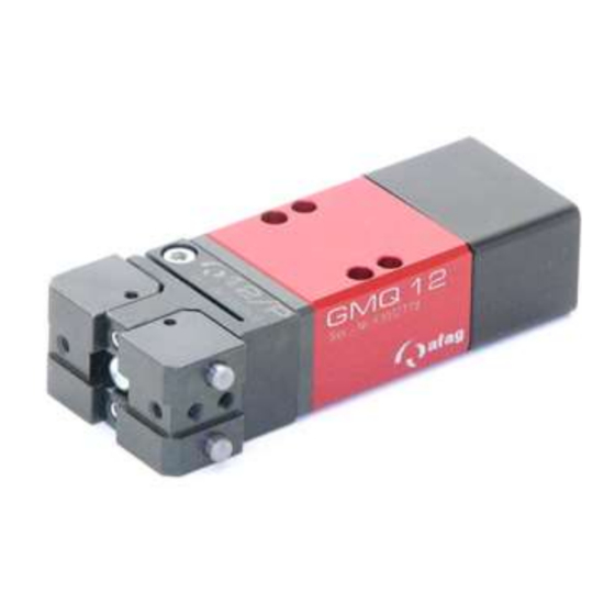
Gripper Module GMQ 12
Rotary Gripper Module GMQ 12-RM 12
Translation of the Original Assembly Instructions EN
GMQ 12/P
◼
GMQ 12/P-01
◼
GMQ 12/K
◼
GMQ 12/P-01-RM 12
◼
GMQ 12/P-RM 12
◼
GMQ 12/K-RM 12
◼
Assembly instructions EN
Order no.: 11000495
Order no.: 50000797
Order No.: 11010496
Order no.: 50002137
Order no.: 50002128
Order no.: 50002131
◼
◼
GMQ 12-RM 12
18.04.2023
◼
GMQ 12/K-RMZ 12
◼
GMQ 12/P-RM 12-SD
◼
GMQ 12/K-RM 12-SD
◼
GMQ 12/P-RMZ 12-SD
◼
GMQ 12/P-01-RMZ 12-SD
◼
◼
V3.0
Order no.: 50002133
Order no.: 50002129
Order no.: 50002132
Order no.: 50002130
Order no.: 50002139
1–57
Advertisement
Table of Contents

Subscribe to Our Youtube Channel
Related Manuals for Afag GMQ 12


Summary of Contents for Afag GMQ 12
- Page 1 Assembly and operating instructions Gripper Module GMQ 12 ◼ Rotary Gripper Module GMQ 12-RM 12 Translation of the Original Assembly Instructions EN GMQ 12/P Order no.: 11000495 GMQ 12/K-RMZ 12 Order no.: 50002133 ◼ ◼ GMQ 12/P-01 Order no.: 50000797...
- Page 2 Your Afag team © Subject to modifications The modules have been designed by Afag Automation AG according to the state of the art. Due to the constant technical development and improvement of our products, we reserve the right to make technical changes at any time.
-
Page 3: Table Of Contents
Technical data ...................... 15 Dimensional drawings ................15 3.1.1 GMQ 12 Gripper Module ..............15 3.1.2 Gripper module GMQ 12 / RM 12 ............16 Technical data .................... 17 3.2.1 GMQ 12 Gripper Module ..............17 3.2.2 Gripper module GMQ 12/RM 12 ............18 Preferred combinations GMQ 12 .............. - Page 4 Fault elimination ....................46 General Notes .................... 46 Safety instructions for troubleshooting ............46 Table Fault causes and remedy GMQ 12 and GMQ 12 / RM12 ....47 Maintenance and repair ..................48 General notes ..................... 48 Safety instructions for maintenance and repair .......... 48 Maintenance activities and maintenance intervals ........
- Page 5 Decommissioning, disassembly, disposal ............54 10.1 Safety instructions for decommissioning, disassembling and disposal ..54 10.2 Decommissioning ..................54 10.3 Disassembly ....................54 10.4 Disposal ...................... 55 Declaration of incorporation ................56 ◼ ◼ ◼ Assembly instructions EN GMQ 12-RM 12 18.04.2023 V3.0 5–57...
-
Page 6: General
This note contains important additional information as well as useful tips for safe, efficient and trouble-free operation of the module. 6 – 57 ◼ ◼ ◼ Assembly instructions EN GMQ 12-RM 12 18.04.2023 V3.0... -
Page 7: Additional Symbols
In these assembly instructions the following symbols are used to highlight instructions, results, references, etc.. Symbol Description Instructions (steps ...) Results of actions References to sections ◼ Enumerations not ordered ◼ ◼ ◼ Assembly instructions EN GMQ 12-RM 12 18.04.2023 V3.0 7–57... -
Page 8: Applicable Documents
▪ Wear parts (e.g. shock absorbers) are excluded from the warranty.* The warranty covers the replacement or repair of defective Afag parts. Further claims are excluded. * However, a customer has a right to a defect-free product. This does also apply to defective accessories and wear parts. -
Page 9: Safety Instructions
Failure to follow the directions and safety instructions given in this instructions manual may result in serious hazards. 2.2 Intended use The GMQ 12 and GMQ 12/RM 12 modules are used for shock-free rotating of loads in non-hazardous atmospheres under the ambient and operating conditions defined for these modules. -
Page 10: Obligations Of The Operator And The Personnel
▪ the operating company shall be solely responsible for such damage, and ▪ Afag does not accept any liability for damage caused by improper use. 2.4 Obligations of the operator and the personnel 2.4.1... -
Page 11: Personnel Requirements
(employer), ▪ check the personal protective equipment for proper condition, and ▪ immediately notify the person responsible on site of any defects found on the personal protective equipment. ◼ ◼ ◼ Assembly instructions EN GMQ 12-RM 12 18.04.2023 V3.0 11–57... -
Page 12: Changes And Modifications
2.7 Changes and modifications No changes may be made to the GMQ module which have not been described in these assembly instructions or approved in writing by Afag Automation AG. Afag Automation AG accepts no liability for unauthorised changes or improper assembly, installation, commissioning, maintenance or repair work. - Page 13 ▪ The operating company is responsible for ensuring that the permissible noise levels are observed. ▪ If the noise level exceeds 85 dB(A) in normal operation, the operator must wear hearing protectors at the workplace. ◼ ◼ ◼ Assembly instructions EN GMQ 12-RM 12 18.04.2023 V3.0 13–57...
-
Page 14: Danger Due To Electricity
Poor or not regularly performed maintenance may cause component failures which may lead to injuries. ▪ The operator must exercise due care and only use trained maintenance maintenance to carry out the activities. 14 – 57 ◼ ◼ ◼ Assembly instructions EN GMQ 12-RM 12 18.04.2023 V3.0... -
Page 15: Technical Data
Technical data Technical data 3.1 Dimensional drawings 3.1.1 GMQ 12 Gripper Module Fig. 1 Dimensional drawing - GMQ 12 ◼ ◼ ◼ Assembly instructions EN GMQ 12-RM 12 18.04.2023 V3.0 15–57... -
Page 16: Gripper Module Gmq 12 / Rm 12
Technical data 3.1.2 Gripper module GMQ 12 / RM 12 Fig. 2 Dimensional drawing - GMQ 12/RM 12 16 – 57 ◼ ◼ ◼ Assembly instructions EN GMQ 12-RM 12 18.04.2023 V3.0... -
Page 17: Technical Data
Technical data 3.2 Technical data 3.2.1 GMQ 12 Gripper Module Fig. 3 Technical data module GMQ 12 ◼ ◼ ◼ Assembly instructions EN GMQ 12-RM 12 18.04.2023 V3.0 17–57... -
Page 18: Gripper Module Gmq 12/Rm 12
Technical data 3.2.2 Gripper module GMQ 12/RM 12 Fig. 4 Technical data gripper module GMQ 12 / RM12 18 – 57 ◼ ◼ ◼ Assembly instructions EN GMQ 12-RM 12 18.04.2023 V3.0... -
Page 19: Preferred Combinations Gmq 12
Technical data 3.3 Preferred combinations GMQ 12 ◼ ◼ ◼ Assembly instructions EN GMQ 12-RM 12 18.04.2023 V3.0 19–57... -
Page 20: Gripper Loads Gmq 12
Technical data 3.4 Gripper loads GMQ 12 Fig. 5 Gripper loads - GMQ 12 20 – 57 ◼ ◼ ◼ Assembly instructions EN GMQ 12-RM 12 18.04.2023 V3.0... -
Page 21: Gripper Drive Gmq 12
Technical data 3.5 Gripper drive GMQ 12 ◼ ◼ ◼ Assembly instructions EN GMQ 12-RM 12 18.04.2023 V3.0 21–57... -
Page 22: Transport, Packaging And Storage
Danger of injury when unpacking the rotary modules! The GMQ modules are packed in the original packaging (cardboard box). The GMQ 12/RM 12 modules are delivered assembled and are not specially packaged. If handled incorrectly, the module may fall out of the box when unpacked and cause limb injuries. -
Page 23: Transport
Environmental damage can be caused by incorrect disposal of the packaging material. ▪ Dispose of the packaging material in an environmentally sensitive way in accordance with the local environmental regulations. ◼ ◼ ◼ Assembly instructions EN GMQ 12-RM 12 18.04.2023 V3.0 23–57... -
Page 24: Storage
▪ Relative air humidity: < 90% non condensing. ▪ Clean the module and protect the blank metal parts against corrosion using the appropriate means. ▪ Protect the module from dirt and dust. 24 – 57 ◼ ◼ ◼ Assembly instructions EN GMQ 12-RM 12 18.04.2023 V3.0... -
Page 25: Design And Description
Design and description Design and description 5.1 Design of GMQ 12 Fig. 7 GMQ 12 Internal or external clamping (exemplary) 1. Screws 6. Countersunk screws 2. Screws 7. Guide pin 3. Gripping jaws 8. Piston 4. Screws 9. Spring 5. Lifting stop ◼... -
Page 26: Product Description
The piston diameter value is 12 mm. A built-in spring (Fig. 4, 1) serves as a gripping force safety device in the depressurised state. The GMQ 12 is designed in such a way that it can be operated in external (Fig. 1), internal (Fig. 2) or double-acting (Fig. 3) mode. -
Page 27: Design Of Gmq 12 / Rm 12
Design and description 5.3 Design of GMQ 12 / RM 12 Fig. 9 Gripper module GMQ 12 / RM 12 1. Gripping jaws 5. Pneumatic connections RM 12 2. Rotary module 6. Pneumatic connections gripper drive 3. Gripper drive 7. Stop screw 4. -
Page 28: Accessories Gmq 12
Design and description 5.5 Accessories GMQ 12 Designation Order no. Stop screw AS 08/15 11011202 Stop screw AS 08/25 11004991 Stop pin M8x1/25 11009229 Shock absorber SD M8x1-2 11004990 INI d6.5x44-Sn1.5-PNP-NO-M8x1 11005439 INI 8x8x38.5-Sn2.0-PNP-NO-M8x1 50338170 28 – 57 ◼ ◼... -
Page 29: Installation, Assembly And Setting
No liability for damages can be assumed for damages caused by improper installation/assembling work of the operator. Chap. 2 „Safety instructions“ in this Also observe the safety instructions in manual. ◼ ◼ ◼ Assembly instructions EN GMQ 12-RM 12 18.04.2023 V3.0 29–57... -
Page 30: Installation & Assembly
There are different mounting options for each module. Fig. 10 Mounting options GMQ 12 & GMQ 12 / RM 12 The GMQ 12 module can be connected to a linear module by attaching a connector (3) (Fig. 10, Fig. 15-16). 30 – 57 ◼... -
Page 31: Module Centering
Installation, assembly and setting 6.2.2 Module centering To ensure high and repetitive accuracy of fit during assembling, operation and exchanging of a module, the components of the Afag modules are provided with a precise module centering unit. Centring bushing and hole grid Designation... -
Page 32: Tightening Torques For Screws
When connecting the compressed air supply for the first time, make sure that all compressed air throttles are closed. Vent the system slowly! The minimum compressed air quality shall comply with the specifications of ISO 8573-1:2010. 32 – 57 ◼ ◼ ◼ Assembly instructions EN GMQ 12-RM 12 18.04.2023 V3.0... - Page 33 P. Compressed air connection 3. Directional control valve (standard 5/2) Pneumatic connections module GMQ 12 / RM 12 Fig. 12 Pneumatic circuit diagram gripper module GMQ 12 / RM 12 1. Gripper drive 4. Maintenance unit 2. Throttle check valve P.
-
Page 34: Mounting The Initiators
10-30 VDC Switching distance: 1.5mm Type Short circuit and reverse polarity protected The proximity switches can only be used with the stop screws of the AS series! 34 – 57 ◼ ◼ ◼ Assembly instructions EN GMQ 12-RM 12 18.04.2023 V3.0... - Page 35 2. Insert the initiator (2) into the initiator holder as far as it will go. 3. Slightly tighten the initiator holder (1). 4. Mount the Cover (3). 5. Mount the connector (4). 6. Carry out function check. The initiator is mounted. ◼ ◼ ◼ Assembly instructions EN GMQ 12-RM 12 18.04.2023 V3.0 35–57...
- Page 36 3. Push the initiator holder (7) with initiator (5) onto the stop screw (8) as far as it will go and clamp it with screw (9). 4. Mount the connector (4). 5. Carry out function check. The initiator is mounted. 36 – 57 ◼ ◼ ◼ Assembly instructions EN GMQ 12-RM 12 18.04.2023 V3.0...
-
Page 37: Assembly/Turning Of The Gripping Jaws
When turning the gripping jaw, make sure that the middle screw (1) is loosened and tightened again after turning so that the gripping jaw is positioned correctly again. This applies to the module GMQ12/P-01. Fig. 16 Turn the gripping jaw ◼ ◼ ◼ Assembly instructions EN GMQ 12-RM 12 18.04.2023 V3.0 37–57... -
Page 38: Manufacture Of The Gripper Fingers
Representation of the gripping fingers (exemplary) The length (L) and the offset (X) of the gripper fingers must not exceed the recommended masses in the gripping force diagrams! 38 – 57 ◼ ◼ ◼ Assembly instructions EN GMQ 12-RM 12 18.04.2023 V3.0... -
Page 39: Settings
Improper adjustment work can cause injuries and damage to property. ▪ Adjustment and conversion work may only be carried out by qualified personnel! Chap. 2 „Safety instructions“ in this Also observe the safety instructions in manual. ◼ ◼ ◼ Assembly instructions EN GMQ 12-RM 12 18.04.2023 V3.0 39–57... -
Page 40: Adjusting The Stop Screw And Stop Pin
Installation, assembly and setting 6.3.2 Adjusting the stop screw and stop pin The GMQ 12 can be equipped with a wide range of stop screws. These must be ordered separately. The stop screw can be combined with an initiator holder and initiator switch 6.5 mm or with an angle initiator holder 8x8 mm for end position detection. -
Page 41: Stroke Adjustment Of The Gmq 12 Grippers
6.3.3 Stroke adjustment of the GMQ 12 grippers The gripper stroke can only be adjusted on the GMQ 12 module. If the GMQ has been converted to internal clamping or the spring has been removed, the stroke stop (1) must be reconnected firmly and flush with the piston rod (2) (Fig. -
Page 42: Conversion Of The Gmq Module
If required, the modules can be converted to another function. Special tools must be used to convert the GMQ 12 / RM 12 modules. Therefore, the GMQ 12 / RM 12 must be sent to Afag for conversion. -
Page 43: Conversion Of The Gmq 12 To Internal Clamping
Installation, assembly and setting 6.4.1 Conversion of the GMQ 12 to internal clamping To convert the GMQ 12 to internal clamping, proceed as follows: 1. Loosen screw (1+2). 2. Dismount the gripping jaw (3). 3. Loosen the screws (4+6). 4. Remove the guide pin (7). -
Page 44: Conversion Of The Gmq 12 To Double-Acting
Installation, assembly and setting 6.4.2 Conversion of the GMQ 12 to double-acting To convert the GMQ 12 to internal clamping, proceed as follows: 1. Loosen screw (1+2). 2. Dismount the gripping jaw (3). 3. Loosen the countersunk screws (6). 4. Remove the guide pin (7). -
Page 45: Commissioning
3. Make sure that there are no persons or tools within the working area of the rotary module. 4. Perform test run: Start with slow traversing movements. Then continue under normal operating conditions. Commissioning is completed. ◼ ◼ ◼ Assembly instructions EN GMQ 12-RM 12 18.04.2023 V3.0 45–57... -
Page 46: Fault Elimination
▪ The due diligence obligations of the user include ensuring that the personnel working on eliminating faults appropriately trained and qualified. Chap. 2 „Safety instructions“ in this Also observe the safety instructions in manual. 46 – 57 ◼ ◼ ◼ Assembly instructions EN GMQ 12-RM 12 18.04.2023 V3.0... - Page 47 Fault elimination 8.3 Table Fault causes and remedy GMQ 12 and GMQ 12 / RM12 Defective components must be replaced exclusively by Afag original spare parts. Fault Possible cause Remedy: ▪ No compressed air ▪ Check connections Gripper does not open/close ▪...
-
Page 48: Maintenance And Repair
▪ Before starting any activities, switch off the media supply (pneumatics) and secure it from being switched on again! Chap. 2 „Safety instructions“ in this Also observe the safety instructions in manual. 48 – 57 ◼ ◼ ◼ Assembly instructions EN GMQ 12-RM 12 18.04.2023 V3.0... -
Page 49: Maintenance Activities And Maintenance Intervals
The modules are almost maintenance-free. Nevertheless, some maintenance work must be carried out to ensure an optimum operating condition of the modules. 9.3.1 Overview of the maintenance points Maintenance points GMQ 12 – GMQ 12 / RM12 Fig. 21 System Interval Maintenance point... -
Page 50: Compressed Air Specifications
If the modules are used in an ionised air environment, there is a risk that exposed parts could corrode. ▪ Always grease exposed parts e.g., flanges, shafts, guides and jaws regularly. ▪ Afag standard lubrication: Staburax NBU8EP (flat guides), Blasolube 301 (piston rods) 9.3.2 Compressed air specifications The modules are lifetime lubricated and can be operated with lubricated or non- lubricated compressed air. -
Page 51: Further Maintenance
Afag for warranty repair within the warranty period. After expiry of the warranty period, the customer may replace or repair defective modules or wear parts himself or send them to the Afag repair service. Please note that Afag does not assume any warranty for modules that have... -
Page 52: Spare Parts Gmq 12
Maintenance and repair 9.4.1 Spare parts GMQ 12 Item Designation Dimensions Supplier number Order no. Housing Afag 11009176 Piston Afag 11002284 Guide pin Afag 11009178 Lifting stop Afag 11009179 Bearing bush Afag 11009180 Cover Afag 11009181 Pressure spring Afag 11002292... -
Page 53: Wear Parts
Wear parts When replacing the wear parts, we recommend that you replace all wear parts at the same time and carefully so that the functional parts are not damaged. Wearing parts set for GMQ 12 - Order no. 11002504 Item Designation... -
Page 54: Decommissioning, Disassembly, Disposal
▪ Disconnect the media supply (electrics, pneumatics) before removing the rotary modules! ▪ Disassembling should only be carried out by qualified personnel! ▪ Only remove module when the controller is switched off and secured! 54 – 57 ◼ ◼ ◼ Assembly instructions EN GMQ 12-RM 12 18.04.2023 V3.0... -
Page 55: Disposal
▪ Electronic parts, electrical scrap, auxiliary and operating materials must be disposed of by approved specialist companies. ▪ Information on proper disposal can be obtained from the responsible local authorities. ◼ ◼ ◼ Assembly instructions EN GMQ 12-RM 12 18.04.2023 V3.0 55–57... -
Page 56: Declaration Of Incorporation
The relevant technical documentation was created according to Annex VII, Part B of the above-mentioned Directive. Authorised representative for compiling the technical documentation: Niklaus Röthlisberger, Product Manager, Afag Automation AG, CH-6144 Zell Place/Date: Zell, 15.06.2022 Siegfried Egli Niklaus Röthlisberger... - Page 57 Afag Automation Americas Afag Automation APAC Schaeff Machinery & Services LLC. Afag Automation Technology (Shanghai) Co., Ltd. 883 Seven Oaks Blvd, Suite 800 Room 102, 1/F, Bldg. 56, City Of Elite Smyrna, TN 37167 No.1000, Jinhai Road, Pudong New District...
Need help?
Do you have a question about the GMQ 12 and is the answer not in the manual?
Questions and answers