Table of Contents
Advertisement
Quick Links
Advertisement
Table of Contents

Subscribe to Our Youtube Channel
Related Manuals for Pfeiffer Vacuum HiPace 700 Plus


Summary of Contents for Pfeiffer Vacuum HiPace 700 Plus
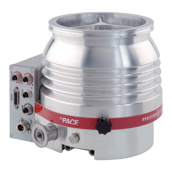
- Page 1 OPERATING INSTRUCTIONS Translation of the Original HIPACE 700 PLUS Turbopump...
- Page 2 Dear Customer, Thank you for choosing a Pfeiffer Vacuum product. Your new turbopump is designed to support you by its performance, its perfect operation and without interfering your individual application. The name Pfeiffer Vacuum stands for high-quality vacuum technology, a comprehensive and complete range of top-quality products and first-class service.
-
Page 3: Table Of Contents
Limits of use of product Proper use Foreseeable improper use Personnel qualification 2.7.1 Ensuring personnel qualification 2.7.2 Personnel qualification for maintenance and repair 2.7.3 Advanced training with Pfeiffer Vacuum Product description Function 3.1.1 Cooling 3.1.2 Rotor bearing 3.1.3 Drive Identifying the product 3.2.1 Product types... - Page 4 Operating modes 6.2.1 Operating without operating unit 6.2.2 Operation via multi-function connection "remote" 6.2.3 Operation via connection "E74" 6.2.4 Operation via Pfeiffer Vacuum control unit 6.2.5 Operation via field bus Switching on the turbopump Operation monitoring 6.4.1 Operating mode display via LED 6.4.2 Temperature monitoring...
- Page 5 List of tables Tbl. 1: Abbreviations used in this document Tbl. 2: Permissible ambient conditions Tbl. 3: Product designation of Pfeiffer Vacuum HiPace turbopumps Tbl. 4: Turbopump features Tbl. 5: Requirements for fastening the turbopumps to the bottom part Tbl. 6:...
- Page 6 Installation of electronic drive unit TC 400 Fig. 23: Spare parts HiPace 700 Plus Fig. 24: HiPace 700 Plus | TC 400 | DN 160 ISO-K Fig. 25: HiPace 700 Plus | TC 400 | DN 160 CF-F Fig. 26:...
-
Page 7: About This Manual
Keep the manual for future consultation. 1.1 Validity This operating instructions is a customer document of Pfeiffer Vacuum. The operating instructions de- scribe the functions of the named product and provide the most important information for the safe use of the device. The description is written in accordance with the valid directives. The information in this op- erating instructions refers to the product's current development status. -
Page 8: Pictographs
This section describes all the stickers on the product along with their meanings. Rating plate (example) The rating plate of the turbopump is located on the lower part D-35614 Asslar Berliner Str. 43 HiPace 700 Plus of the vacuum pump. Mod. PM PXX XXX Rating plate of the electronic drive unit... -
Page 9: Abbreviations
About this manual 1.3.4 Abbreviations Abbreviation Meaning in this document Flange: Metal-sealed connector in accordance with ISO 3669 Diameter value (in mm) Direct current Nominal diameter as size description Rotation speed value of a vacuum pump (frequency, in rpm or Hz) High compression Handheld Programming Unit. -
Page 10: Safety
Safety 2 Safety 2.1 General safety information The following 4 risk levels and 1 information level are taken into account in this document. DANGER Immediately pending danger Indicates an immediately pending danger that will result in death or serious injury if not observed. ►... - Page 11 Safety Risks during installation DANGER Danger to life from electric shock Power supply packs that are not specified or are not approved will lead to severe injury to death. ► Make sure that the power supply pack meets the requirements for double isolation between mains input voltage and output voltage, in accordance with IEC 61010-1 IEC 60950-1 and IEC 62368-1.
- Page 12 ► Take suitable safety precautions on-site for the compensation of the occurring torques. ► Before installing a vibration compensator, you must first of all contact Pfeiffer Vacuum. WARNING Danger of cut injuries from unexpected start up.
- Page 13 Safety Risks during maintenance, decommissioning and disposal WARNING Danger to life from electric shock during maintenance and service work The device is only completely de-energized when the mains plug has been disconnected and the tur- bopump is at a standstill. There is a danger to life from electric shock when making contact with live components.
-
Page 14: Safety Precautions
► Follow the installation instructions for this turbopump. ► Observe the requirements regarding stability and design of the counter flange. ► Use only original accessories or fixing material approved by Pfeiffer Vacuum for the installation. WARNING Danger to life from poisoning where toxic process media leak from damaged connections Sudden twisting of the turbopump in the event of a fault causes fittings to accelerate. -
Page 15: Limits Of Use Of Product
Safety ► Never put the device into operation with the high vacuum connection open. ► Keep lines and cables away from hot surfaces (> 70°C). ► Never fill or operate the unit with cleaning agents or cleaning agent residues. ► Do not carry out your own conversions or modifications on the unit. ►... -
Page 16: Personnel Qualification
Such training must ensure that individuals are capable of carrying out the required activi- ties and work steps safely and properly. 2.7.2 Personnel qualification for maintenance and repair Advanced training courses Pfeiffer Vacuum offers advanced training courses to maintenance levels 2 and 3. 16/62... -
Page 17: Advanced Training With Pfeiffer Vacuum
─ Customer with Pfeiffer Vacuum service training ─ Pfeiffer Vacuum service technician 2.7.3 Advanced training with Pfeiffer Vacuum For optimal and trouble-free use of this product, Pfeiffer Vacuum offers a comprehensive range of courses and technical trainings. For more information, please contact Pfeiffer Vacuum technical training. -
Page 18: Product Description
Product description 3 Product description 3.1 Function The turbopump forms a compact unit with the electronic drive unit. The Pfeiffer Vacuum power supply packs are used for voltage supply. The properties designation "Plus" designates turbopumps with particularly low-vibration action and a low magnetic stray field. -
Page 19: Identifying The Product
ID no. 000021320. 3.2.1 Product types The product designation of Pfeiffer Vacuum turbopumps from the HiPace series is composed of the family name, the size (which is based on the pumping speed of the vacuum pump) and, if required, an additional feature description. -
Page 20: Transportation And Storage
► Do not stack the products. ► Wear protective equipment, e.g. safety shoes. Recommendation Pfeiffer Vacuum recommends keeping the transport packaging and original protective cov- Safe transport of the product ► Transport the turbopump only within the permissible temperature limits. -
Page 21: Installation
Installation 5 Installation The installation of the turbopump and its fastening is of outstanding importance. The rotor of the turbo- pump revolves at very high speed. In practice it is not possible to exclude the risk of the rotor touching the stator (e.g. due to the penetration of foreign bodies into the high vacuum connection). The kinetic energy released acts on the housing and on the anchoring of the turbopump within fractions of a sec- ond. -
Page 22: Connecting The High Vacuum Side
● Make sure that all the torques generated if the rotor blocks suddenly, are absorbed by the system on the operator side and the high vacuum connection. ● Only use the approved mounting kits of Pfeiffer Vacuum for the high vacuum connec- tion of the turbopump. -
Page 23: Considering Earthquake Protection
Safety connections, customer-side 5.3.3 Using a splinter shield or protective screen Pfeiffer Vacuum centering rings with splinter shield or protective screen in the high vacuum flange pro- tect the turbopump against foreign matter from the vacuum chamber. The pumping speed of the turbo- pump reduces according to the passage guide values and the size of the high vacuum flange. -
Page 24: Using The Vibration Compensator
4. Observe the fastening of the ISO flanges. 5.3.5 Mounting orientations Pfeiffer Vacuum turbopumps of the HiPace series are suitable for use with dry compressing backing pumps for mounting in all orientations. ► When using oil-sealed backing pumps, avoid backflow from the fore-vacuum range. -
Page 25: Attaching Iso-K Flange To Iso-F
Flange connection ISO-K to ISO-F, bracket screws Connection with bracket screw 1. For the connection of the turbopump, use only the approved mounting kits from Pfeiffer Vacuum. 2. Connect the flange with the components of the mounting kit according to the figure. -
Page 26: Attaching Iso-F Flange To Iso-F
Connection of the stud screw and tapped hole 1. Only use the approved mounting kits of Pfeiffer Vacuum for the connection of the turbopump. 2. Screw in the required number of stud screws with the shorter end in the holes on the counter flange. -
Page 27: Attaching Cf Flange To Cf-F
Connection of the hexagon head screw and tapped hole 1. Only use the approved mounting kits of Pfeiffer Vacuum for the connection of the turbopump. 2. Attach the turbopump with centering ring to the counter flange according to the figure. -
Page 28: Fig. 12: Flange Connection Cf-F, Hexagon Head Screw And Through Hole
Connection of the hexagon head screw and through holes 1. For the connection of the turbopump, use only the approved mounting kits from Pfeiffer Vacuum. 2. If used: Insert the protective screen or splinter shield with clamping lugs downwards in the turbo- pump high vacuum flange. -
Page 29: Connecting The Fore-Vacuum Side
Connection of the stud screw and through hole 1. For the connection of the turbopump, use only the approved mounting kits from Pfeiffer Vacuum. 2. If used: Insert the protective screen or splinter shield with clamping lugs downwards in the turbo- pump high vacuum flange. -
Page 30: Cooling Water Connection
1. With rigid pipe connections, include bellows to attenuate external vibrations. 2. Install a fore-vacuum connection with small flange components, e.g. connection elements and pipe components DN 25 ISO-KF from the Pfeiffer Vacuum Components Shop. 3. Implement measures to counteract the backflow of operating fluids or condensate from the fore- vacuum area. -
Page 31: Tbl. 8: Requirements On The Cooling Water Composition
Installation Parameter Cooling water Carbonate hardness, max. 10 °dH 12.53 °e 17.8 °fH 178 ppm CaC0 Chloride content, max. 100 mg/l Sulfate content, max. 240 mg/l Carbonic acid content, max. not detectable Ammonia content, max. not detectable Electrical conductivity, max. 500 µS/cm Particle size, max. -
Page 32: Connecting Accessories
● The use of other accessories for turbopumps is possible and requires settings in the configuration of the electronic drive unit. ● The desired accessory output is configured via RS-485 using Pfeiffer Vacuum control units or a PC. ● For detailed information see the “Electronic drive unit TC 400” or “Electronic drive unit TC 700”... -
Page 33: Grounding The Turbopump
► Do not carry out your own conversions or modifications on the unit. ► Ensure the integration into an Emergency Off safety circuit. 5.7.1 Grounding the turbopump Pfeiffer Vacuum recommends connecting a suitable grounding cable to discharge applicative interfer- ences. Fig. 17:... -
Page 34: Fig. 18: Connecting Electronic Drive Unit To Power Supply Pack
2. Make sure that the power supply pack main switch is off prior to connection. 3. Use a suitable connection cable from the Pfeiffer Vacuum accessories range. 4. Insert the connecting cable into the connection "DCin" on the electronic drive unit and close the bayonet lock. -
Page 35: Operation
Simultaneous loading by means of high drive power (gas throughput, fore-vacuum pressure), high heat radiation, or strong magnetic fields results in uncontrolled heating of the rotor and can destroy the vacuum pump. ► Consult Pfeiffer Vacuum before combining varying loads on the vacuum pump. Lower limit val- ues apply. NOTICE... -
Page 36: Operating Modes
Instructions for operation without control panel 1. Use only the approved Pfeiffer Vacuum mating plug with bridges on the connection of the elec- tronic drive unit. 2. Switch on the mains supply of the turbopump only immediately before operation. -
Page 37: Switching On The Turbopump
6.4.1 Operating mode display via LED LEDs on the electronic drive unit show the basic operating states of the vacuum pump. A differentiated error and warning display is only possible for operation with the Pfeiffer Vacuum control unit or a PC. 37/62... -
Page 38: Temperature Monitoring
Operation Symbol LED status Display Meaning Currentless On, flashing "pumping station OFF", rotation speed ≤ 60 rpm Green On, inverse flashing "pumping station ON", set rotation speed not reached On, constant "pumping station ON", set rotation speed reached On, flashing "pumping station OFF", speed >... -
Page 39: Tbl. 13: Factory Settings For Delayed Venting In Turbopumps
General information for fast venting We recommend fast venting of larger volumes in 4 steps. 1. Use a Pfeiffer Vacuum venting valve for the turbopump, or match the valve cross-section to the size of the recipient and maximum venting rate. -
Page 40: Maintenance
5. Change the operating fluid reservoir at least every 4 years. 6. Have Pfeiffer Vacuum Service replace the rotor bearing of the turbopump at least every 4 years. 7. Consult with Pfeiffer Vacuum Service about shorter maintenance intervals for extreme loads or im- pure processes. -
Page 41: Replacing Operating Fluid Reservoir
Scan the QR code or click here to view Service Level 1 Replacement of operating flu- id reservoir. You can find the safety data sheet in the Pfeiffer Vacuum Download Center. Prerequisites ● Turbopump off ● Vacuum system vented to atmospheric pressure ●... -
Page 42: Assembling Operating Fluid Reservoir
Maintenance Fig. 19: Removing operating fluid reservoir 1 O-ring Operating fluid reservoir 2 Closing cap Injection tip 3 Hexagon socket screw Protective cap Removing operating fluid reservoir 1. Wear laboratory gloves to avoid skin contact. 2. Place the turbopump on the closed high vacuum flange. 3. -
Page 43: Replacing Electronic Drive Unit
Maintenance Fig. 20: Assembling operating fluid reservoir 1 Operating fluid reservoir Closing cap 2 Injection tip Hexagon socket screw 3 O-ring Protective cap Installing operating fluid reservoir without capillary rods ● Note that the capillary rods are not used when replacing the operating fluid reservoir. Assembling operating fluid reservoir 1. -
Page 44: Removing Electronic Drive Unit
Maintenance NOTICE Property damage from electrostatic discharge Neglecting the electrostatic hazard for electronic components results in their damage or destruction ► Implement ESD safety measures at the workstation. ► Observe EN 61340 "Protection of electronic devices from electrostatic phenomena". Backing up settings made by the customer The factory operating parameters are always preset in replacement units. -
Page 45: Installing The Electronic Drive Unit
5. Set the parameter [P:777] to the required value of the nominal rotation speed in Hertz. Alternative to adjusting the nominal rotation speed confirmation A Pfeiffer Vacuum SpeedConfigurator for the one-time immediate setting of parameter [P:777] is included with the replacement units. -
Page 46: Decommissioning
2. Clean the turbopump externally with a lint-free cloth and a little isopropanol. 3. If necessary, arrange for Pfeiffer Vacuum Service to completely clean the turbopump. 4. Observe the total running time of the turbopump and if necessary, arrange for Pfeiffer Vac- uum Service to replace the bearing. -
Page 47: Recycling And Disposal
● Help to reduce the wastage of natural resources. ● Prevent contamination. 9.1 General disposal information Pfeiffer Vacuum products contain materials that you must recycle. ► Dispose of our products according to the following: – Iron – Aluminium –... -
Page 48: Malfunctions
► Follow the installation instructions for this turbopump. ► Observe the requirements regarding stability and design of the counter flange. ► Use only original accessories or fixing material approved by Pfeiffer Vacuum for the installation. WARNING Risk of injury caused by the turbopump breaking away with the vibration compensator in the event of a malfunction Sudden jamming of the rotor generates high destructive torques in accordance with ISO 27892. -
Page 49: Tbl. 15: Troubleshooting Turbopumps
● Reduce the process gas load. ● Rotor not running ● Check the turbopump for noise development smoothly, defective ● Contact Pfeiffer Vacuum Service. bearing ● Run-up time setpoint ad- ● Use a control unit to extend the set value run-up justed too low time [P:700]. -
Page 50: Service Solutions By Pfeiffer Vacuum
We are always focused on perfecting our core competence – servicing of vacuum components. Once you have purchased a product from Pfeiffer Vacuum, our service is far from over. This is often exactly where service begins. Obviously, in proven Pfeiffer Vacuum quality. - Page 51 Service solutions by Pfeiffer Vacuum 5. Prepare the product for transport in accordance with the provisions in the contamination declaration. a) Neutralize the product with nitrogen or dry air. b) Seal all openings with blind flanges, so that they are airtight.
-
Page 52: Spare Parts Hipace 700 Plus
Spare parts HiPace 700 Plus 12 Spare parts HiPace 700 Plus Fig. 23: Spare parts HiPace 700 Plus Posi- Designation Order number Remark Pieces tion Electronic drive unit refer to the rating depending on the connec- TC 400 plate tion panel... -
Page 53: Accessories
Optionally with splinter shield or protective screen. Power supply packs and control units Power supply packs for optimal voltage supply of Pfeiffer Vacuum products are characterized by their compact size and adapted power supply with maximum reliability. Control units are used to check and adjust operating parameters. - Page 54 Accessories Selection field Part number Mounting kit for DN 160 ISO-F, including coated centering ring, splinter shield, PM 016 466 -T stud screws Mounting kit for DN 160 ISO-F, including coated centering ring, protective PM 016 467 -T screen, stud screws Elastomer seal, FKM, DN 160 CF 402DFL160-S2 Elastomer seal, FKM, DN 160 CF...
-
Page 55: Tbl. 17: Hipace 700 Accessories
Accessories Selection field Part number Power separator for RS-485 PT 348 132 -T TIC 010, adapter for two sensors PT R70 000 RPT 010, digital Piezo/Pirani sensor PT R71 100 IKT 010, digital cold cathode sensor, low current PT R72 100 IKT 011, digital cold cathode sensor, high current PT R73 100 Y-connector M12 for RS-485... -
Page 56: Technical Data And Dimensions
Technical data and dimensions 14 Technical data and dimensions 14.1 General This section describes the basis for the technical data of Pfeiffer Vacuum turbopumps. Technical data Maximum values refer exclusively to the input as a single load. ● Specifications according to PNEUROP committee PN5 ●... - Page 57 Technical data and dimensions Type designation HiPace® 700 Plus HiPace® 700 Plus HiPace® 700 Plus Compression ratio for H 4 · 10 4 · 10 4 · 10 Compression ratio for He 3 · 10 3 · 10 3 · 10 Compression ratio for N >...
-
Page 58: Substances In Contact With The Media
Tbl. 21: Materials that make contact with the process media 14.4 Dimensions Dimensions in mm Ø8 DN 160 ISO-K DN 25 ISO-KF / G 1/4” M8 (6x) 145.5 Fig. 24: HiPace 700 Plus | TC 400 | DN 160 ISO-K 58/62... -
Page 59: Fig. 25: Hipace 700 Plus | Tc 400 | Dn 160 Cf-F
Ø 8 DN 160 CF-F DN 25 ISO-KF / G 1/4“ M8 (6x) 145.5 Fig. 25: HiPace 700 Plus | TC 400 | DN 160 CF-F Ø 8 DN 160 ISO-F DN 25 ISO-KF / G 1/4“ M8 (6x) 145.5 Fig. -
Page 60: Ec Declaration Of Conformity
DIN EN 61010-1 : 2020 DIN EN IEC 63000 : 2019 The authorized representative for the compilation of technical documents is Mr. Tobias Stoll, Pfeiffer Vacuum GmbH, Berliner Straße 43, 35614 Asslar, Germany. Signature: Pfeiffer Vacuum GmbH Berliner Straße 43... -
Page 61: Declaration Of Conformity
ISO 21360-4:2018 IEC 61010-1+A1:2010 IEC 63000:2018 The manufacturer's authorized representative in the United Kingdom and the authorized agent for compiling the technical documentation is Pfeiffer Vacuum Ltd, 16 Plover Close, In- terchange Park, MK169PS Newport Pagnell. Signature: Pfeiffer Vacuum GmbH Berliner Straße 43...
Need help?
Do you have a question about the HiPace 700 Plus and is the answer not in the manual?
Questions and answers