Table of Contents
Advertisement
Quick Links
Advertisement
Table of Contents

Subscribe to Our Youtube Channel
Related Manuals for Pfeiffer Vacuum DUO 11 DC


Summary of Contents for Pfeiffer Vacuum DUO 11 DC
- Page 1 OPERATING INSTRUCTIONS Translation of the Original DUO 11 DC Rotary vane pump...
- Page 2 Dear Customer, Thank you for choosing a Pfeiffer Vacuum product. Your new rotary vane pump is designed to support you by its performance, its perfect operation and without interfering your individual application. The name Pfeiffer Vacuum stands for high-quality vacuum technology, a comprehensive and complete range of top-quality products and first-class service.
-
Page 3: Table Of Contents
Table of contents Table of contents About this manual Validity Applicable documents Target group Conventions 1.4.1 Instructions in the text 1.4.2 Pictographs 1.4.3 Stickers on the product 1.4.4 Abbreviations Safety General safety instructions Safety instructions Safety precautions Safety precautions for vacuum pumps with magnetic coupling Product usage limits Proper use Foreseeable improper use... - Page 4 Decommissioning the vacuum pump for longer periods Recommissioning Disposing of the vacuum pump Malfunctions Service solutions from Pfeiffer Vacuum Spare parts 11.1 Ordering spare parts packs 11.1.1Maintenance kit 1 – maintenance level 1 11.1.2Radial shaft seal ring set – maintenance level 2 11.1.3Maintenance kit 2 –...
-
Page 5: About This Manual
Keep the manual for future consultation. 1.1 Validity These operating instructions are for customers of Pfeiffer Vacuum. They describe the function of the designated product and provide the most important information for safe usage of the product. The de- scriptions comply with applicable directives. All information provided in these operating instructions refer to the current development status of the product. -
Page 6: Stickers On The Product
Rating plate (example) VACUUM D-35641 Asslar The rating plate is located on the front right side next to the sight glass. Mod.: DUO 11 DC Mod.-Nr.: PK D59 XXX Ser.- Nr.: 0014440 max. 9 m /h (N ) 2 Inland 45 0.5 l... -
Page 7: Abbreviations
About this manual 1.4.4 Abbreviations Abbreviation Explanation DC version Direct Current M version Version with magnetic coupling Oil mist filter (Oil Mist Eliminator) Operating fluid return line (Oil Drain Kit) RSSR Radial shaft seal ring width across flats Tbl. 2: Abbreviations used in this document 7/50... -
Page 8: Safety
Safety 2 Safety 2.1 General safety instructions This document includes the following four risk levels and one information level. DANGER Imminent danger Indicates a hazardous situation which, if not avoided, will result in death or serious injury. ► Instructions on avoiding the hazardous situation WARNING Possibly imminent danger Indicates a hazardous situation which, if not avoided, could result in death or serious injury. - Page 9 Safety WARNING Danger of poisoning from toxic vapors Igniting and heating synthetic operating fluid generates toxic vapors. Danger of poisoning if inhaled. ► Observe the application instructions and precautions. ► Do not allow tobacco products to come into contact with the operating fluid. Risks during operation WARNING Danger of poisoning due to emission of toxic process gases from the exhaust...
- Page 10 Safety CAUTION Danger of injury from moving parts After a power failure or a standstill as a result of overheating, the motor restarts automatically. There is a risk of injury to fingers and hands if they enter the operating range of rotating parts. ►...
-
Page 11: Safety Precautions
Safety 2.3 Safety precautions Duty to provide information on potential dangers The product holder or user is obliged to make all operating personnel aware of dan- gers posed by this product. Every person who is involved in the installation, operation or maintenance of the product must read, understand, and adhere to the safety-related parts of this docu- ment. -
Page 12: Foreseeable Improper Use
(F4, F5, A113) as operating fluid. ► Adhere to the installation, commissioning, operating, and maintenance instructions. ► Do not use any accessory parts other than those recommended by Pfeiffer Vacuum. 2.7 Foreseeable improper use Improper use of the product invalidates all warranty and liability claims. Improper use is any, even unin- tended, use, which is contrary to the product purpose;... -
Page 13: Product Description
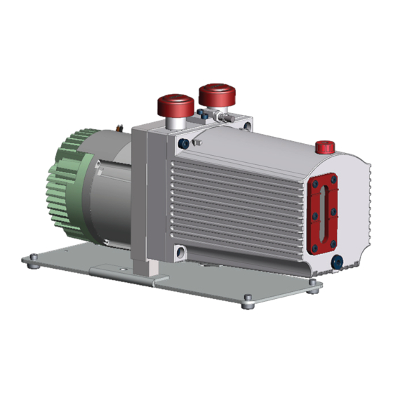
3.1 Identifying the product Procedure ► To ensure clear identification of the product when communicating with Pfeiffer Vacuum, always keep all of the information on the rating plate to hand. ► Note motor-specific data on the separately attached mototr rating plate. -
Page 14: Operating Principle
Product description 3.4 Operating principle Fig. 3: UnoLine and DuoLine operating principle Housing Suction chamber Rotor Exhaust (outlet) Vane Vacuum flange (inlet) The rotary vane pump is an oil-sealed rotary displacement pump. The pumping system is made up of the housing, the eccentrically mounted rotor, and the centrifugally- and spring-loaded radially sliding vanes, which divide the suction chamber into multiple chambers. -
Page 15: Transportation And Storage
3. Lift the vacuum pump out of the transport packaging by hand. 4.2 Storing the vacuum pump Pfeiffer Vacuum recommends storing the products in their original transport pack- aging. Procedure 1. Fill the vacuum pump with operating fluid up to the upper edge of the sight glass. - Page 16 Transportation and Storage 3. Make sure that the gas ballast valve is closed. 4. Store the vacuum pump only in dry, dust-free rooms, within the specified ambient conditions. 5. In rooms with humid or aggressive atmospheres: Hermetically seal the vacuum pump together with a drying agent in a plastic bag.
-
Page 17: Installation
Installation 5 Installation 5.1 Installing the vacuum pump ● Indoors, protected from dust deposits Installation location ● Outdoors, protected from direct weather influences Installation altitude max. 2000 m Orientation as level as possible; max. permissible angle of inclination: ±10° Ambient temperature -20 °C to +40 °C Relative air humidity max. -
Page 18: Connecting The Vacuum Side
6. Connect both flanges with a circlip (DN 16 ISO-KF). 7. Protect the vacuum pump from sucking in impurities through suitable measures. 8. Use a separator or filter from the Pfeiffer Vacuum line of accessories if necessary. 5.3 Connecting the exhaust side... - Page 19 Installation CAUTION Danger of injury from bursting as a result of high pressure in the exhaust line Faulty or short exhaust lines cause hazardous situations, e.g. exhaust pressure increase. There is a danger of bursting. Injuries caused by flying fragments, the escaping of high pressure, and damage to the unit cannot be excluded.
-
Page 20: Install Ome 16 S
5.3.1 Install OME 16 S With a high gas throughput, Pfeiffer Vacuum recommends the optional use of an oil mist filter (OME 16 S). It prevents oil mist from escaping at the exhaust and collects the oil separated in the hous- ing of the separator. -
Page 21: Connecting The Voltage Supply
Installation 6 (7) Fig. 9: Install the ODK to OME 16 S OME 16 S Locking cap Coupling I Operating fluid return hose Locking screw Spiral spring Coupling II Required tools ● Allan key (included in the OME 16 S shipment) ●... -
Page 22: Motor Protection
Product-specific performance data are not achieved. All liability and warranty claims against Pfeiffer Vacuum are also excluded. ► Only use approved operating fluids. ► Only use other application-specific operating fluids after consultation with Pfeiffer Vacuum. Approved operating fluid ● Inland 45 (standard operating fluid) - Page 23 Installation Fig. 10: Filling the operating fluid Filling screw for operating fluid O-ring Consumable ● Operating fluid of the vacuum pump Required tool ● Allen key, WAF 5 mm Filling the operating fluid 1. Unscrew the operating fluid filler screw. 2.
-
Page 24: Operation
Operation 6 Operation 6.1 Putting the vacuum pump into operation Before switching on 1. Check the operating fluid in the sight glass. 2. Compare the frequency specifications on the rating plate with the available supply voltage. 3. Adequately protect the vacuum pump from sucking in impurities through appropriate measures (e.g. -
Page 25: Operating The Rotary Vane Pump With Gas Ballast
Operation 6.3 Operating the rotary vane pump with gas ballast NOTICE Risk of damage from condensation in vacuum pump During operation without gas ballast, condensation may form as a result of the vapor compatibility of the vacuum pump being exceeded. ► Pump condensable vapors only when the vacuum pump is warm and the gas ballast valve open. ►... -
Page 26: Gas Ballast Valve With Solenoid Valve
Operation For some processes, Pfeiffer Vacuum recommends the addition of flushing gas to dilute the process gas, and prevent condensation in the vacuum pump. Fig. 12: Gas ballast valve with flushing gas connection (option) Valve body Allen head screw (2x) -
Page 27: Refilling Operating Fluid
Operation Fig. 13: Gas ballast inlet with solenoid valve Flushing gas connection, G 1/8" Solenoid valve Classification advanced Gas Ballast Valve with Solenoid Valve Order number PK 194 343 -U Connection G 1/8" Operating voltage: DC 24 V Input voltage: tolerance ±10 % Power consumption Pressure max. -
Page 28: Switching Off The Vacuum Pump
– Tightening torque: max. 0.3 Nm 6.5 Switching off the vacuum pump Pfeiffer Vacuum rotary vane pumps have an integral safety valve on the intake side. The safety valve automatically closes from a differential pressure of ≥250 hPa between the exhaust and intake sides, when the vacuum pump is switched on, and vents the vacuum pump. -
Page 29: Maintain Vacuum In The Vacuum Chamber
Operation 6.5.2 Maintain vacuum in the vacuum chamber NOTICE Contamination from operating fluid backflow After the vacuum pump is switched off, there is a risk that the connected vacuum system can become contaminated by backflow. The safety valve on the vacuum pump is not suitable for longer-term seal- ing. -
Page 30: Maintenance
► Dismantle the vacuum pump for inspection, away from the system if necessary. NOTICE Danger of property damage from improper maintenance Unprofessional work on the vacuum pump will lead to damage for which Pfeiffer Vacuum accepts no liability. ► We recommend taking advantage of our service training offering. -
Page 31: Checklist For Inspection And Maintenance
This safety note applies to drive system disassembly in pump versions with magnetic coupling. 7.2 Checklist for inspection and maintenance Pfeiffer Vacuum recommends that all maintenance work is carried out by the manufacturer’s service de- partment. No warranty or liability claims are accepted on the part of Pfeiffer Vacuum, if you ●... -
Page 32: Changing The Operating Fluid
► Wear protective equipment. ► Use a suitable collection receptacle. Pfeiffer Vacuum recommends determining the precise service life of the oper- ating fluid in the first operating year. The usable life may deviate from the reference value specified depending on ther- mic and chemical loads, and the accumulation of suspended particles and conden- sate in the operating fluid. -
Page 33: Draining The Operating Fluid
● It is possible to detect thermal aging of the operating fluid from its color number (applies to mineral oils only). Safety data sheets You can obtain the safety data sheets for operating fluids from Pfeiffer Vacuum on request, or from the Pfeiffer Vacuum Download Center. -
Page 34: Rinsing And Cleaning The Rotary Vane Vacuum Pump
7.3.2 Rinsing and cleaning the rotary vane vacuum pump Cleaning by changing the operating fluid Pfeiffer Vacuum recommends, in cases of heavy contamination with process resi- dues, cleaning the inside of the vacuum pump with several operating fluid changes. Required tools ●... -
Page 35: Cleaning The Gas Ballast Valve
Maintenance Fig. 16: Remove/fit rotary vane vacuum pump cap Allen head screw (2x) stand Pumping system O-ring Remove the cap 1. Drain the operating fluid. 2. Unscrew both Allen head screws from the cap. 3. Remove the cap from the stand in axial direction. –... - Page 36 Maintenance Valve housing Cam plate O-ring Countersink screw (2×) Tappet Head Cylinder bolt Countersink screw Required tools ● Allen key, WAF 2 mm ● Circlip pliers J0 ● Calibrated torque wrench (tightening factor ≤ 2.5) Dismantle gas ballast valve 1. Unscrew the countersink screws (2x). 2.
-
Page 37: Gas Ballast Valve With Flushing Gas Connection (Option)
Maintenance 7.4.2 Gas ballast valve with flushing gas connection (option) Fig. 18: Gas ballast valve with flushing gas connection (option) Circlip Screw (2×) Spindle O-ring O-ring (2x) Hose connection O-ring Screw cap Valve housing O-ring Valve flap Required tools ● Allen key, WAF 2.5 mm ●... -
Page 38: Changing The Operating Fluid Type
Maintenance 7.5 Changing the operating fluid type Possibilities for changing the operating fluid type The operating fluid type can be changed between mineral operating fluid – P3 – and synthetic operating fluid – D1 – only. It is not possible to change from P3/D1 to F4/F5 or vice versa. -
Page 39: Decommissioning
7. In rooms with humid or aggressive atmospheres: Hermetically seal the vacuum pump together with a drying agent in a plastic bag. 8. For longer storage periods (> 2 years), Pfeiffer Vacuum recommends changing the operating fluid again prior to recommissioning. -
Page 40: Malfunctions
► Wear personal protective equipment if necessary. NOTICE Danger of property damage from improper maintenance Unprofessional work on the vacuum pump will lead to damage for which Pfeiffer Vacuum accepts no liability. ► We recommend taking advantage of our service training offering. - Page 41 ● Refilling operating fluid ● Leak in system ● Locate and eliminate the leak. ● Vacuum pump is dam- ● Contact Pfeiffer Vacuum service. aged Pumping speed of vacuum ● The intake line is not suit- ● Make sure that connections are...
-
Page 42: Service Solutions From Pfeiffer Vacuum
We are consistently striving to perfect our core competence, service for vacuum components. And our service is far from over once you’ve purchased a product from Pfeiffer Vacuum. It often enough really just begins then. In proven Pfeiffer Vacuum quality, of course. - Page 43 ERKLÄRUNG KONTAMINIERUNG Then send your product to your local Service Center. You will receive a confirmation message/a quotation from Pfeiffer Vacuum. For all service orders, our General Terms and Conditions of Sales and Supply General Terms and Conditions of Repair and Maintenance apply to vacuum equipment and components.
-
Page 44: Spare Parts
PK E02 057 -T Set of vanes PK E08 032 -T Tbl. 8: Spare parts pack Duo 11 DC 11.1.1 Maintenance kit 1 – maintenance level 1 Order no.: PK E01 050 CT Maintenance kit 1 contains: ● Filler and drain screw seals for one operating fluid change ●... -
Page 45: 2Radial Shaft Seal Ring Set - Maintenance Level
Spare parts Item no. Designation Size Shipment O-ring, FPM 16.5 × 1.5 Valve flap O-ring, FPM 6 × 2.2 O-ring, FPM 11 × 1.5 O-ring, FPM 8 × 2 Tbl. 9: Content of maintenance kit 1 11.1.2 Radial shaft seal ring set – maintenance level 2 The radial shaft seal ring set contains all parts for changing the shaft seal ring and operating fluid: ●... -
Page 46: Technical Data And Dimensions
Technical data and dimensions 12 Technical data and dimensions 12.1 General Basis for the technical data of Pfeiffer Vacuum rotary vane pumps: ● Specifications according to PNEUROP committee PN5 ● ISO 21360; 2007: “Vacuum technology - Standard methods for measuring vacuum-pump perform- ance - General description”... -
Page 47: Dimensions
Inland 45 Operating fluid filling 0.5 l Switch New Mains cable included Weight: with motor 9 kg Tbl. 12: Technical data, Duo 11 DC 12.3 Dimensions All dimensions in mm DN16 ISO-KF 27.5 ±1 ±1 Fig. 20: Dimension diagram DUO 11 DC... -
Page 48: Accessories
Accessories 13 Accessories Accessories for Duo 11 DC Order no. SAS 16, DN 16 ISO-KF PK Z60 506 KAS 16, Condensate Separator PK Z10 003 OME 16 M, Oil Mist Separator PK Z40 003 Oil Return Unit from OME 16 M to Duo 1.6, 3, 6, 11, Uno 6... -
Page 49: Declaration Of Conformity
Restriction of the use of certain hazardous substances 2011/65/EU The authorized representative for the compilation of technical documents is Mr. Sebas- tian Oberbeck, Pfeiffer Vacuum GmbH, Berliner Straße 43, 35614 Aßlar, Germany. DuoLine Duo 11 DC | Duo 11 M DC...
Need help?
Do you have a question about the DUO 11 DC and is the answer not in the manual?
Questions and answers