
Related Manuals for Pfeiffer Vacuum MVP 040-2


Summary of Contents for Pfeiffer Vacuum MVP 040-2
- Page 1 OPERATING INSTRUCTIONS Translation of the Original MVP 040-2 ∣ MVP 070-3 ∣ MVP 070-3 C Diaphragm pump...
- Page 2 Dear Customer, Thank you for choosing a Pfeiffer Vacuum product. Your new diaphragm pump is designed to support you with its performance, perfect operation and without impacting your individual application. The name Pfeiffer Vacuum stands for high-quality vacuum technology, a comprehensive and complete range of top-quality products and first-class service.
-
Page 3: Table Of Contents
Operating the vacuum pump with gas ballast Pumping condensable vapors Switching off the vacuum pump Maintenance Maintenance instructions Checklist for inspection and maintenance Replacing device fuses Replacing diaphragms and valves of MVP 040-2 7.4.1 Dismantling vacuum pump MVP 040-2 3/58... - Page 4 Table of contents 7.4.2 Removing diaphragms from MVP 040-2 7.4.3 Installing diaphragms for MVP 040-2 7.4.4 Installing vacuum pump MVP 040-2 Replacing diaphragms and valves of MVP 070-3 7.5.1 Dismantling vacuum pump MVP 070-3 7.5.2 Removing diaphragms from MVP 070-3 7.5.3 Installing diaphragms for MVP 070-3...
- Page 5 Accessories MVP 070-3 C Tbl. 13: Conversion table: Pressure units Tbl. 14: Conversion table: Units for gas throughput Tbl. 15: Technical data, MVP 040-2 Tbl. 16: Technical data, MVP 070-3 Tbl. 17: Technical data MVP 070-3 C Tbl. 18: Materials that make contact with the process media...
- Page 6 List of figures List of figures Fig. 1: Position of the stickers on the product Fig. 2: Design of vacuum pump MVP 040-2 Fig. 3: Design of vacuum pump MVP 070-3 Fig. 4: Design of vacuum pump MVP 070-3 C Fig.
-
Page 7: About This Manual
Keep the manual for future consultation. 1.1 Validity This operating instructions is a customer document of Pfeiffer Vacuum. The operating instructions de- scribe the functions of the named product and provide the most important information for the safe use of the device. The description is written in accordance with the valid directives. The information in this op- erating instructions refers to the product's current development status. -
Page 8: Pictographs
Pictographs used in the document indicate useful information. Note 1.3.3 Stickers on the product This section describes all the stickers on the product along with their meanings. Rating plate Rating plate for diaphragm pump MVP 040-2 Mod. MVP 040-2 2021/07 PK T01 210 xxxxxxxxxx max. -
Page 9: Abbreviations
About this manual Fig. 1: Position of the stickers on the product 1 Warranty seal (2×) Voltage range warning sign 2 “Hot surface” warning sign Rating plate of the diaphragm pump Incl. the 2 warning signs 1.3.4 Abbreviations Abbreviation Meaning in this document Alternating current Corrosive gas version Nominal diameter (diamètre nominal) -
Page 10: Safety
Safety 2 Safety 2.1 General safety information The following 4 risk levels and 1 information level are taken into account in this document. DANGER Immediately pending danger Indicates an immediately pending danger that will result in death or serious injury if not observed. ►... - Page 11 ► Install suitable touch protection if the vacuum pump is unrestrictedly accessible. ► Allow the vacuum pump to cool down before carrying out any work. ► Contact Pfeiffer Vacuum for suitable touch protection in system solutions. CAUTION Health hazard from increased noise emission Operation without silencer leads to higher noise emissions.
- Page 12 ► Install suitable touch protection if the vacuum pump is unrestrictedly accessible. ► Allow the vacuum pump to cool down before carrying out any work. ► Contact Pfeiffer Vacuum for suitable touch protection in system solutions. CAUTION Danger of injury from moving parts After a power failure or a standstill as a result of overheating, the motor restarts automatically.
-
Page 13: Safety Precautions
Safety Risks during maintenance, decommissioning and in the event of malfunctions WARNING Danger to life from electric shock during maintenance and service work The vacuum pump is only completely de-energized when the mains plug has been disconnected. There is a danger to life from electric shock when making contact with live components. ►... -
Page 14: Limits Of Use Of The Product
► Use the vacuum pump for vacuum generation only. ► Adhere to the installation, commissioning, operating, and maintenance instructions. ► Do not use any accessory parts other than those recommended by Pfeiffer Vacuum. 2.6 Foreseeable improper use Improper use of the product invalidates all warranty and liability claims. Any use that is counter to the purpose of the product, whether intentional or unintentional, is regarded as improper use;... -
Page 15: Personnel Qualification
Such training must ensure that individuals are capable of carrying out the required activi- ties and work steps safely and properly. 2.7.2 Personnel qualification for maintenance and repair Advanced training courses Pfeiffer Vacuum offers advanced training courses to maintenance levels 2 and 3. Adequately trained individuals are: 15/58... -
Page 16: Advanced Training With Pfeiffer Vacuum
─ Customer with Pfeiffer Vacuum service training ─ Pfeiffer Vacuum service technician 2.7.3 Advanced training with Pfeiffer Vacuum For optimal and trouble-free use of this product, Pfeiffer Vacuum offers a comprehensive range of courses and technical trainings. For more information, please contact Pfeiffer Vacuum technical training. -
Page 17: Product Description
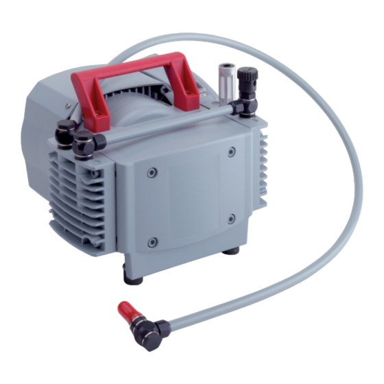
The gas flow causes the valves to open and close automatically. The pump unit is directly connected to the drive motor. 10 11 Fig. 2: Design of vacuum pump MVP 040-2 1 Handle Vacuum connection 2 Exhaust with silencer... -
Page 18: Drive
Once the motor has cooled down, the vacuum pump restarts automatically. 3.1.2 Pumping system Diaphragm pump MVP 040-2 has 2 pumping stages. Diaphragm pump MVP 070-3 (C) has 4 pumping stages. 3.1.3 Cooling The diaphragm pump is convection-cooled. -
Page 19: Connections
Connection description of the diaphragm pump 3.3 Identifying the product ► To ensure clear identification of the product when communicating with Pfeiffer Vacuum, always keep all of the information on the rating plate to hand. ► Learn about certifications through test seals on the product or at www.certipedia.com... -
Page 20: Transportation And Storage
Transportation and Storage 4 Transportation and Storage 4.1 Transporting the vacuum pump WARNING Danger of serious injury due to falling objects Due to falling objects there is a risk of injuries to limbs through to broken bones. ► Take particular care and pay special attention when transporting products manually. ►... -
Page 21: Installation
6. Keep the specifications on the motor rating plate visible and freely accessible. 5.2 Connecting the vacuum side NOTICE Property damage from contaminated gases Pumping gases that contain contamination damages the vacuum pump. ► Use suitable filters or separators from the Pfeiffer Vacuum range of accessories, to protect the vacuum pump. 21/58... -
Page 22: Connect Exhaust Side
Installation Installation and operation of accessories Pfeiffer Vacuum offers a series of special, compatible accessories for its diaphragm pumps. ● Information and ordering options for approved accessories can be found online. ● Described accessories are not included in the shipment. -
Page 23: Connecting To The Mains Power Supply
Installation 3. Depending on the pump type, use PVC or metallic hoses with flange connections from the Pfeiff- er Vacuum component shop. 4. Option: In case of higher gas throughputs, mount an exhaust line. 5. Route the piping downwards from the vacuum pump, to prevent condensate return. 6. - Page 24 Installation Required tool ● Slot screwdriver Accessories required ● Mains cable Changing the voltage range 1. The mains voltage must be determined on-site each time before the vacuum pump is installed or moved to a different location. 2. Disconnect the vacuum pump from the mains. 3.
-
Page 25: Operation
► Install suitable touch protection if the vacuum pump is unrestrictedly accessible. ► Allow the vacuum pump to cool down before carrying out any work. ► Contact Pfeiffer Vacuum for suitable touch protection in system solutions. NOTICE Vacuum pump damage caused by overpressure Mixing up the connections causes overpressure overload. -
Page 26: Operating The Vacuum Pump With Gas Ballast
Operation Prerequisite ● Required mains connection established Switching on the vacuum pump 1. If required, switch the vacuum pump on in each pressure range at the mains switch. 2. Allow the vacuum pump to warm up prior to process start, with the vacuum connection closed. The vacuum pump achieves the specified throughput and final pressure values once the operating tem- perature has been reached. -
Page 27: Pumping Condensable Vapors
Operation Fig. 7: Gas ballast valve 1 Cap of gas ballast valve Gas ballast valve Behavior with process gases with condensable vapors ► Operate the vacuum pump with gas ballast, i.e. with the gas ballast valve open. Open gas ballast valve ►... -
Page 28: Switching Off The Vacuum Pump
Operation Installing the flushing gas connection Use of the optional flushing gas connection improves expulsion of condensate, and the pump attains the specified final vacuum again more quickly. 1. Remove cap from gas ballast valve. 2. Push flushing gas connection over gas ballast valve. 3. -
Page 29: Maintenance
► Do not use any alcohol or other cleaning agents to clean the diaphragms and valves. NOTICE Danger of property damage from improper maintenance Unprofessional work on the vacuum pump will lead to damage for which Pfeiffer Vacuum accepts no liability. ► We recommend taking advantage of our service training offering. -
Page 30: Checklist For Inspection And Maintenance
We recommend that Pfeiffer Vacuum Service carry out maintenance work at level 2. If the specified intervals are exceeded, or if maintenance work is carried out improperly, no war- ranty or liability claims are accepted on the part of Pfeiffer Vacuum. This also applies wher- ever parts other than original spare parts are used. -
Page 31: Replacing Device Fuses
Maintenance 7.3 Replacing device fuses WARNING Danger to life from electric shock during maintenance and service work The vacuum pump is only completely de-energized when the mains plug has been disconnected. There is a danger to life from electric shock when making contact with live components. ►... -
Page 32: Replacing Diaphragms And Valves Of Mvp 040-2
Maintenance 7.4 Replacing diaphragms and valves of MVP 040-2 NOTICE Property damage from incorrect installation Change in dead volume due to incorrect installation of the original spacer disks impairs the final vac- uum or leads to bearing damage. ► During disassembly, keep the existing spacer disks separate per installation location. -
Page 33: Dismantling Vacuum Pump Mvp 040-2
11 Cylinder screws Valves made from FPM (brown) 12 Housing cover, outlet side O-rings 7.4.1 Dismantling vacuum pump MVP 040-2 Prerequisites ● Vacuum pump vented to atmospheric pressure ● Supply voltage switched off ● Drive motor disconnected from mains and secured against activation ●... -
Page 34: Removing Diaphragms From Mvp 040-2
6. Remove head cover with valves. 7. Remove valves from head cover. 8. If the valves are sticking to the housing cover, carefully detach the valves. 9. Inspect valves for damage. 7.4.2 Removing diaphragms from MVP 040-2 Prerequisite ● Head cover and valves dismantled Required consumables ●... -
Page 35: Replacing Diaphragms And Valves Of Mvp 070-3
Maintenance Required tools ● Open-end wrench, WAF 17 ● Allen key, WAF 5 ● Calibrated torque wrench (tightening factor ≤ 1.6) Procedure 1. Replace wear parts (valves) according to spare part package. 2. Insert valves into head cover. – Ensure correct mounting orientation and materials of valves. 3. -
Page 36: Dismantling Vacuum Pump Mvp 070-3
Maintenance 18 17 10 9 Fig. 10: Individual parts MVP 070-3 N Nose on head cover Head cover diaphragm head 1 1 O-rings Diaphragm clamping disk 2 Valves made from FPM (brown) Diaphragm pair 3 Head cover diaphragm head 4 Diaphragm support disk 4 Silencer Spacer disks... -
Page 37: Removing Diaphragms From Mvp 070-3
Maintenance 7.5.2 Removing diaphragms from MVP 070-3 NOTICE Damage to diaphragms due to incorrect handling Incorrect handling or using the wrong tools when changing diaphragms can cause damage to dia- phragms of the vacuum pump. ► Do not use pointed or sharp-edged tools. ►... -
Page 38: Installing Vacuum Pump Mvp 070-3
Maintenance 3. Place 2 individual diaphragms on top of one another with the rough sides together. – The labeled sides of both diaphragms must be legible. 4. Place diaphragm pair and diaphragm support disk on the square of the diaphragm clamping disk. 5. -
Page 39: Dismantling Vacuum Pump Mvp 070-3 C
Maintenance General information regarding replacement of diaphragms and valves ● Diaphragms and valves can be replaced completely independently of one another. ● Head cover can be removed complete with valve clusters and interconnections. ● Complete head cover can be removed from one side of pump when replacing valves only. ●... -
Page 40: Removing Diaphragms From Mvp 070-3 C
Maintenance Fig. 13: Hose clamps and clamping claws 1 Hose clamp Clamping claw on valve cluster Procedure 1. Open integral hinge on connection holder. 2. Loosen oval-head screw on connection holder by no more than one full rotation ensuring that it does not unscrew completely from the hexagon nut. -
Page 41: Installing Diaphragms For Mvp 070-3 C
Maintenance Fig. 14: Function of diaphragm key Procedure 1. Unscrew interior hexagon socket screws from head cover. 2. Remove head cover together with valve clusters and connections. 3. Carefully bend up side of diaphragm. 4. Attach diaphragm key to diaphragm support disk. 5. -
Page 42: Installing Vacuum Pump Mvp 070-3 C
Maintenance 7.6.4 Installing vacuum pump MVP 070-3 C NOTICE Damage to valves during the exchange process Incorrect installation of valves can cause damage to the valves as a result of sticking to the head cov- ► Make sure that the valves have the correct mounting orientation. ►... -
Page 43: Checking The Final Pressure
Maintenance 12. Tighten countersunk screws on clamping claws. – Tightening torque: 3 Nm 13. Fit hose for hose connection. 14. Fit hose clamp on connection hose. 15. Tighten hose clamp on connection hose with flat pliers. 16. Fit head cover hood. 17. -
Page 44: Decommissioning
Decommissioning 8 Decommissioning Before shutting down the vacuum pump, observe the following instructions to adequately protect the in- terior of the vacuum pump (suction chamber) from corrosion: Procedure for temporary vacuum pump shutdowns 1. Allow the vacuum pump to run on for 5 to 10 minutes with the vacuum connection open to allow any condensate that may be present to be removed from the vacuum pump. -
Page 45: Recycling And Disposal
– Fluoroelastomers (FKM) – Potentially contaminated components that come into contact with media 9.2 Dispose of diaphragm pumps Pfeiffer Vacuum diaphragm pumps contain materials that you must recycle. 1. Disconnect the electronic drive unit. 2. Dismantle the motor. 3. Decontaminate the components that come into contact with process gases. -
Page 46: Malfunctions
► Wear personal protective equipment if necessary. NOTICE Danger of property damage from improper maintenance Unprofessional work on the vacuum pump will lead to damage for which Pfeiffer Vacuum accepts no liability. ► We recommend taking advantage of our service training offering. -
Page 47: Tbl. 8: Troubleshooting On Diaphragm Pumps
● Valves dirty or defec- ● If necessary, clean or replace the tive valves and diaphragms. ● Motor fan defective ● Contact Pfeiffer Vacuum Service. ● Connection rod or mo- ● Contact Pfeiffer Vacuum Service. tor bearing defective Tbl. -
Page 48: Service Solutions By Pfeiffer Vacuum
We are always focused on perfecting our core competence – servicing of vacuum components. Once you have purchased a product from Pfeiffer Vacuum, our service is far from over. This is often exactly where service begins. Obviously, in proven Pfeiffer Vacuum quality. - Page 49 Service solutions by Pfeiffer Vacuum 5. Prepare the product for transport in accordance with the provisions in the contamination declaration. a) Neutralize the product with nitrogen or dry air. b) Seal all openings with blind flanges, so that they are airtight.
-
Page 50: Spare Parts Packages
► Install original spare parts only. ► When ordering the inspection set, observe the respective part number of the diaphragm pump. Spare parts package Part number Remark MVP 040-2 MVP 070-3 MVP 070-3 C Overhaul kit PU E22 013 -T... -
Page 51: Accessories
PK 050 110 Mains cable 115/230 V without plug, rubber connector (right angle), 3 m PK 050 111 Screw-in flange DN 16 ISO-KF / G1/4" incl. seal (for MVP 040-2, MVP 070-3 inlet/ PK 050 114 -T outlet) Flushing gas connection DN 6 / DN 10 (for MVP 040-2 / MVP 070-3 C) PK 050 299 Tbl. -
Page 52: Technical Data And Dimensions
Technical data and dimensions 14 Technical data and dimensions 14.1 General Basis for the technical data of Pfeiffer Vacuum diaphragm pumps: ● Specifications according to PNEUROP committee PN5 ● ISO 21360:2012: “Vacuum technology - Standard methods for measuring vacuum-pump perform- ance - General description”... - Page 53 -10 – 60 °C -10 – 60 °C Degree of pollution – – Weight 11.4 kg 11.4 kg Tbl. 15: Technical data, MVP 040-2 Type designation MVP 070-3 MVP 070-3 MVP 070-3 MVP 070-3 MVP 070-3 Part number PK T01 310...
-
Page 54: Substances In Contact With The Media
Weight 14.3 kg 14.3 kg Tbl. 17: Technical data MVP 070-3 C 14.3 Substances in contact with the media Pump parts MVP 040-2 MVP 070-3 MVP 070-3 C Housing cover Aluminum alloy (AlMg- Aluminum alloy (AlMg- Head cover Aluminum alloy (AlMg-... -
Page 55: Dimensions
Hose Polyethylene (PE) Polyethylene (PE) PTFE Tbl. 18: Materials that make contact with the process media 14.4 Dimensions Gasballast Schlauch 1000 mm Schalldämper Gas ballast Silencer Hose 1000 mm G1/4“ 22.5 Fig. 16: Dimensions MVP 040-2 Dimensions in mm 55/58... -
Page 56: Dimensions Mvp
Technical data and dimensions Schlauch 1000 mm Schalldämpfer Hose 1000 mm Silencer G1/4“ Fig. 17: Dimensions MVP 070-3 Dimensions in mm Gasballast Kleinflansch DN 16 Schlauchwelle DN 10 Gas ballast Small flange DN 16 Hose nozzle DN 10 Fig. 18: Dimensions MVP 070-3 C Dimensions in mm 56/58... -
Page 57: Declaration Of Conformity
DIN EN 61010-1:2011 DIN EN 61326-1:2013 IEC 61010-1:2010 (Ed. 3) The authorized representative for the compilation of technical documents is Dr. Adrian Wirth, Pfeiffer Vacuum GmbH, Berliner Straße 43, 35614 Asslar, Germany. Signature: Pfeiffer Vacuum GmbH Berliner Straße 43 35614 Asslar Germany (Daniel Sälzer)
Need help?
Do you have a question about the MVP 040-2 and is the answer not in the manual?
Questions and answers