Advertisement
Quick Links
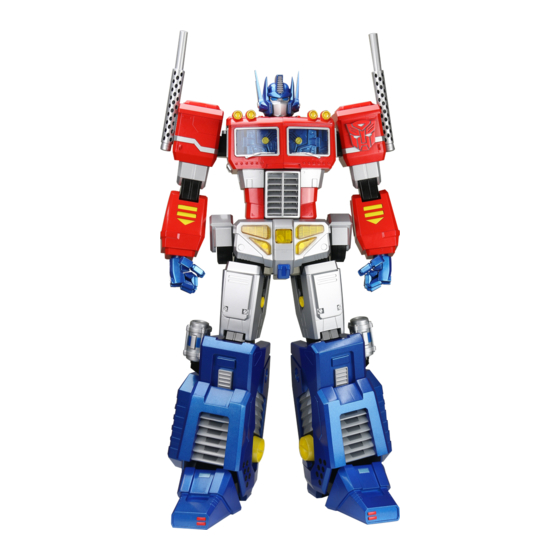
Pack 01
B U I L D
I N S T R U C T I O N S
ASSEMBLING THE HEAD – PART 1
ASSEMBLING THE HEAD – PART 5
ASSEMBLING THE HEAD – PART 2
ASSEMBLING THE CHEST
ASSEMBLING THE HEAD – PART 3
TESTING THE ELECTRONICS
ASSEMBLING THE HEAD – PART 4
TRANSFORMERS and HASBRO and all related trademarks and logos are trademarks of Hasbro, Inc. ©2023 Hasbro.
Advertisement

Subscribe to Our Youtube Channel
Related Manuals for Agora Models OPTIMUS PRIME Pack 01


Summary of Contents for Agora Models OPTIMUS PRIME Pack 01
- Page 1 Pack 01 B U I L D I N S T R U C T I O N S ASSEMBLING THE HEAD – PART 1 ASSEMBLING THE HEAD – PART 5 ASSEMBLING THE HEAD – PART 2 ASSEMBLING THE CHEST ASSEMBLING THE HEAD –...
- Page 2 Advice from the experts Please keep ALL unused screws as they may be required in a later stage. Please make sure you don’t mix up the screws. They look quite similar, but the threads do vary slightly. Using the wrong screws may damage the parts. When securing parts together using multiple screws, fit each screw loosely to ensure all the parts are correctly aligned before gently tightening them firmly, but not overtight, in the order in which you placed them.
- Page 3 Pack 1 : Building the Head & Chest AGORAMODELS OPTIMUS PRIME...
- Page 4 Pack 1 Parts T R A Y 1 PWM 2x6mm x10 TR-1-50 TR-1-03 TR-1-51 TR-1-40 TR-1-39 TR-1-25 TR-1-01 TR-1-11 TR-1-30 TR-1-12 TR-1-23 TR-1-26-2 TR-1-21 TR-1-18 TR-1-20 TR-1-02 TR-1-24 TR-1-26-1 TR-1-17 TR-1-22 TR-1-14 x2 TR-1-27 TR-1-16 TR-1-19 TR-1-08 TR-1-28 TR-1-29 TR-1-15 TR-1-52 TR-1-58 TR-1-53...
- Page 5 Pack 1 Parts T R A Y 2 TR-1-55 x2 TR-1-41 TR-1-05 TR-1-54 x2 TR-1-66/67 TR-1-61 TR-1-45 TR-1-07 TR-1-10 PWB 2x6mm x26 TR-1-42 TR-1-06 TR-1-33 x4 TR-1-34 x4 TR-1-09 TR-1-59 TR-1-60 TR-1-43 TR-1-44 TR-1-04 TR-1-13 AGORAMODELS OPTIMUS PRIME...
- Page 6 Pack 1 Parts T R A Y 3 TR-1-47 TR-1-63 x4 TR-1-56 TR-1-57 TR-1-46 x4 TR-1-38 TR-1-36 TR-1-49 TR-1-37 TR-1-35 TR-1-64 TR-1-62 TR-1-48 AGORAMODELS OPTIMUS PRIME...
- Page 7 Assembling the Head – Part 1 TR-1-40 TR-1-39 S T E P 1 Glue TR-1-40 as shown in TR-1-01 red in the image above right before pushing into place on TR-1-39. TR-1-39 Push TR-1-39 into place on TR-1-01 TR-1-12 TR-1-01 TR-1-11 S T E P 2 Glue parts TR-1-11 and TR-1-12 as shown in red, above...
- Page 8 Assembling the Head – Part 1 2x PWM TR-1-03 S T E P 3 Push assembly A onto TR-1-03 and fix with 2x PWM screws. Your completed assembly, shown in the image on the right, will be referred to as assembly B AGORAMODELS OPTIMUS PRIME...
- Page 9 Assembling the Head – Part 2 S T E P 1 TR-1-20 TR-1-26-1 Place TR-1-21 on TR-1-26-1, then place TR-1-20 onto TR-1-26-1. The assembly you have created will be referred to as assembly C. TR-1-21 S T E P 2 Place assembly C in between TR-1-17 and TR-1-18 as shown.
- Page 10 Assembling the Head – Part 3 TR-1-58 TR-1-16 S T E P 4 Push TR-1-58 and TR-1-16 together as shown. Glue the areas shown in red, then push TR-1-16 onto TR-1-19. This assembly will be referred to as E. TR-1-19 TR-1-16 TR-1-53 TR-1-52...
- Page 11 Assembling the Head – Part 3 2x PWB S T E P 6 Secure the parts together using 2 x PWB screws. The mask has now been attached to the head. AGORAMODELS OPTIMUS PRIME...
- Page 12 Assembling the Head – Part 4 TR-1-24 TR-1-25 S T E P 1 TR-1-25 Push TR-1-25 onto TR-1-24. Place TR-1-23 and TR-1-22 onto TR-1-25 as shown. TR-1-22 TR-1-23 TR-1-30 2x TR-1-34 2x TR-1-33 S T E P 2 Push 2 x TR-1-33 through F and fix in place using 2x TR-1-34 nuts.
- Page 13 Assembling the Head – Part 4 S T E P 3 Take part TR-1-26-2 and plug it into the socket on D. TR-1-26-2 S T E P 4 Take part TR-1-27 and fix it to E using 1x PWB screw. TR-1-27 S T E P 5 Attach E to D by sliding the...
- Page 14 Assembling the Head – Part 4 TR-1-50 S T E P 6 Push TR-1-50 onto F, then fix it to G using 3 x PWB screws. 3x PWB S T E P 7 Push TR-1-51 onto F and then fix it to G using 3 x PWB screws.
- Page 15 Assembling the Head – Part 4 S T E P 7 c o n t . . . These two images show how the cable should run when the parts have been fixed together. S T E P 8 Push 1x TR-1-33 bolt through G as shown and secure with 1x TR-1-34 nut.
- Page 16 Assembling the Head – Part 4 2x TR-1-14 TR-1-02 S T E P 9 Glue TR-1-02 as shown TR-1-02 above right, before fixing 2x TR-1-14 into position, then push TR-1-02 onto G. 4x PWB S T E P 1 0 Fix TR-1-02 in place using 4x PWB screws.
- Page 17 Assembling the Head – Part 4 S T E P 1 1 Fix B to G using 4x PWB screws. 4x PWB Assembling the Head – Part 5 S T E P 1 Glue TR-1-04 as shown, then push TR-1-09 and TR-1-04 TR-1-06 onto either side of TR-1-04.
- Page 18 Assembling the Head – Part 5 TR-1-10 TR-1-05 TR-1-07 S T E P 3 Glue TR-1-05 as shown, then push TR-1-07 and TR-1-10 onto either side. Secure the assembly onto H using 1x PWB screw. S T E P 4 TR-1-08 Glue TR-1-08 before pushing onto H as shown.
- Page 19 Assembling the Head – Part 5 TR-1-13 TR-1-41 S T E P 5 Glue TR-1-41 as shown in 5a, then push onto H. Then glue TR-1-41 as shown in 5b and push TR-1-13 into place (the number 1 faces inside). TR-1-13 TR-1-41 S T E P 6...
- Page 20 Assembling the Head – Part 5 P a r t 5 C o m p l e t e AGORAMODELS OPTIMUS PRIME...
- Page 21 Assembling the Chest TR-1-63 TR-1-47 S T E P 1 Cut one part of TR-1-47 from the sprue. Insert 1x TR-1-63 into TR-1-47 (Length = 200mm) as shown in 1a. TR-1-62 TR-1-46 S T E P 2 Cut 1x part TR-1-62 from the sprue (2a), push it onto TR-1-46, then place on I.
- Page 22 Assembling the Chest TR-1-49 S T E P 3 Cut 1x TR-1-49 from the sprue (3a) and glue as shown in 3b, then push onto I. Repeat steps 1–3 to make 4 sets. TR-1-56 S T E P 4 Push 2x sets of I into TR-1-56 (marked No.1, circled above) until they click into place.
- Page 23 Assembling the Chest S T E P 5 Route the cables as shown. S T E P 6 Place TR-1-54 onto TR-1-37 and fix in place using TR-1-54 2x PWB screws. TR-1-37 2x PWB S T E P 7 Glue TR-1-55 as shown in 7a, then position on TR-1-54.
- Page 24 Assembling the Chest S T E P 9 TR-1-36 Position TR-1-36 onto J, then secure it in place using 4x PWM screws. 4x PWM S T E P 1 0 TR-1-43 Align the notch on TR-1-59 with the recess on TR-1-43 (highlighted, and shown in 10a &...
- Page 25 Assembling the Chest TR-1-61 S T E P 1 2 Cut 1x TR-1-45 and 1x TR-1-61 from their sprues, match their shapes and push together as shown in 12. TR-1-61 fits into the recess on TR-1-45. TR-1-45 S T E P 1 3 Place the assembly from step 12 into position on J as shown.
- Page 26 Assembling the Chest S T E P 1 6 Place TR-1-54 on TR-1-38 and secure in place using TR-1-54 2x PWB screws. TR-1-38 2x PWB S T E P 1 7 Glue TR-1-55 as shown in 17a, then position onto TR-1-55 TR-1-54, checking that the cable projects through the...
- Page 27 Assembling the Chest S T E P 2 0 Push TR-1-60 into the recess on TR-1-44 to assemble the right side- window. TR-1-44 TR-1-60 S T E P 2 1 Position the right side-window onto L. Cut another 1x TR-1-42 from the sprue, glue as shown in 21b then fix into place on the...
- Page 28 Assembling the Chest S T E P 2 4 Push the assembled window from step 23 onto L until it clicks into place. The left and right side- windows are now complete! C H E S T C O M P L E T E AGORAMODELS OPTIMUS PRIME...
-
Page 29: Testing The Electronics
Testing the Electronics S T E P 1 TR-1-29 Take the battery holder TR-1-29 and the PCB TR-1-28. Insert 4x AA batteries into the battery holder. TR-1-28 S T E P 2 Connect the plug into the socket on the PCB as shown. - Page 30 Testing the Electronics S T E P 5 Take the left & right-chest windows and connect the cables, one at a time, to the PCB. The four headlights should light up. Here we show just one of the headlights, please check all four are working correctly. S T A G E C O M P L E T E S T A G E C O M P L E T E P A C K 1 C O M P L E T E...
Need help?
Do you have a question about the OPTIMUS PRIME Pack 01 and is the answer not in the manual?
Questions and answers