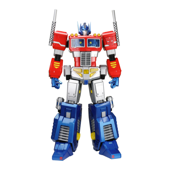
Agora Models OPTIMUS PRIME Build Instructions
Hide thumbs
Also See for OPTIMUS PRIME:
- Build instructions (50 pages) ,
- Build instructions (50 pages) ,
- Build instructions (13 pages)

Related Manuals for Agora Models OPTIMUS PRIME


Summary of Contents for Agora Models OPTIMUS PRIME
- Page 1 Pack 07 B U I L D I N S T R U C T I O N S ASSEMBLING THE LEFT FOOT ASSEMBLING THE RIGHT FOOT TRANSFORMERS and HASBRO and all related trademarks and logos are trademarks of Hasbro, Inc. ©2023 Hasbro.
- Page 2 Always protect the paint finish on components by placing a cutting mat, sheet of white paper or soft cloth on your work surface. Left and Right! When building your Optimus Prime, the left or right hand side refers to each side as viewed by Optimus Prime. Optimus Prime’s left arm is on the viewer’s right.
- Page 3 Pack 7 Parts T R A Y 1 TR-7-19 TR-7-18 TR-7-16 M 3x14mm TR-7-22 TR-7-27 (nut 3) TR-7-01 2.3x6mm M 3x10mm TR-7-21 TR-7-21 TR-7-01 M 3x8mm TR-7-23 TR-7-17 TR-7-14 TR-7-13 TR-7-13 TR-7-26 TR-7-25 AGORAMODELS OPTIMUS PRIME...
- Page 4 Pack 7 Parts T R A Y 2 TR-7-10 TR-7-11 TR-7-03 TR-7-06 TR-7-07 TR-7-20 TR-7-23 TR-7-04 TR-7-15 TR-7-23 TR-7-02 TR-7-12 AGORAMODELS OPTIMUS PRIME...
- Page 5 Pack 7 Parts T R A Y 3 TR-7-03 TR-7-11 TR-7-10 TR-7-08 TR-7-09 TR-7-20 TR-7-23 TR-7-05 TR-7-15 TR-7-23 TR-7-02 TR-7-12 AGORAMODELS OPTIMUS PRIME...
- Page 6 TR-7-18 S T E P 1 Place TR-7-16 on TR-7-18. Attach TR-7-19 over the screw posts on TR-7-18 and secure in place with 2x PB2.3x6 mm screws. Repeat to make 2 sets. PB 2.3x6 TR-7-19 A x2 AGORAMODELS OPTIMUS PRIME...
- Page 7 PB 2.3x6 TR-7-17 S T E P 3 Lower TR-7-17 on top of TR-7-13. Secure in place from the underside using 2x PB2.3x6 mm screws. B x2 S T E P 4 Repeat to make two sets. AGORAMODELS OPTIMUS PRIME...
- Page 8 Slide B into A as shown. Repeat to make two sets. TR-7-23 TR-7-26 M3x8 S T E P 6 Take the left foot assembled in Pack 6. Attach TR-7-23. Thread 2x TR-7-26 washers onto 2x M3x8 mm screws and secure the part in place. AGORAMODELS OPTIMUS PRIME...
- Page 9 S T E P 8 Thread 4x TR-7-25 washers onto 4x M3x14 screws. Place them in the screw holes indicated then secure from the opposite side using 4x TR-7-27 nuts. M3x14 TR-7-25 TR-7-27 D Front D Back AGORAMODELS OPTIMUS PRIME...
- Page 10 Assembling the Left Foot S T E P 9 Attach D to the left foot. S T E P 1 0 Using 2x TR-7-25 washers and 2x TR-7-25 M3x10 screws, secure the parts in place. M3x10 AGORAMODELS OPTIMUS PRIME...
- Page 11 Z. Secure them using 6x PB2.3x6 mm screws. PB2.3x6 S T E P 1 2 Push TR-7-23 into Z. Using 2x TR-7-25 washers and 2x M3x10 mm screws, secure the part in place. TR-7-23 M3x10 TR-7-25 AGORAMODELS OPTIMUS PRIME...
- Page 12 S T E P 1 3 Attach TR-7-15 to Z and secure using 2x PB2.3x6 mm screws. TR-7-07 PB2.3x6 S T E P 1 4 Place TR-7-07 over the raised screw posts on Z and secure using 4x PB2.3x6 mm screws. AGORAMODELS OPTIMUS PRIME...
- Page 13 Place TR-7-06 over the screw posts on the opposite side of Z and secure in place using 3x PB2.3x6mm screws S T E P 1 6 Gently push the leg parts back by 20 degrees to continue the next steps. AGORAMODELS OPTIMUS PRIME...
- Page 14 Take assembly C and align the screw holes inside the foot. Secure in place using 2x PB2.3x6 mm screws. PB2.3x6 S T E P 1 8 Align the two upper scew holes and screw posts and fix together using 2x PB2.3x6 mm screws. AGORAMODELS OPTIMUS PRIME...
- Page 15 Assembling the Left Foot S T E P 1 9 Attach part TR-7-02 to Z and fix it using 2x TR-7-25 washers and 2x M3x10 mm screws. TR-7-02 M3x10 TR-7-25 AGORAMODELS OPTIMUS PRIME...
- Page 16 2x PB2.3x6 mm screws. PB2.3x6 TR-7-21 S T E P 2 1 Attach part TR-7-23 to Z ensuring the screws holes are aligned. Fix in place using 2x TR-7-25 washers and 2x M3x10 mm screws. TR-7-23 M3x10 TR-7-25 AGORAMODELS OPTIMUS PRIME...
- Page 17 Assembling the Left Foot S T E P 2 2 Attach part TR-7-03 to Z and fix using 2x TR-7-25 washers and 2x M3x10 mm screws. TR-7-03 M3x10 TR-7-25 AGORAMODELS OPTIMUS PRIME...
- Page 18 S T E P 2 3 Attach part TR-7-20 to Z and secure using 2x PB2.3x6 mm screws. PB2.3x6 TR-7-20 S T E P 2 4 Attach part TR-7-10 to Z and secure using 4x PB2.3x6 mm screws. TR-7-10 PB2.3x6 AGORAMODELS OPTIMUS PRIME...
- Page 19 Assembling the Left Foot S T E P 2 5 Attach part TR-7-11 to Z and secure using 3x PB2.3x6 mm screws. PB2.3x6 TR-7-11 Left foot complete! Left foot complete! AGORAMODELS OPTIMUS PRIME...
- Page 20 TR-7-05 TR-7-12 S T E P 2 Take part TR-7-01 (marked R ) and attach TR-7-12 and TR-7-05. Note – the pin shown in red on 05 slides within the recess shown in red on 01 (2a). AGORAMODELS OPTIMUS PRIME...
- Page 21 M3x14 mm screws. Place them in the screw holes indicated then secure from the opposite side using 4x TR-7-27 nuts. M3x14 TR-7-25 TR-7-27 E Front E Back S T E P 4 Attach E to the right foot. AGORAMODELS OPTIMUS PRIME...
- Page 22 S T E P 6 Take 3x parts TR-7-22 and place them over the screw holes on Z. Secure them using 6x PB2.3x6 mm screws. Note: pay attention to the position of the cable (6b). TR-7-22 TR-7-22 PB2.3x6 AGORAMODELS OPTIMUS PRIME...
- Page 23 S T E P 7 Push TR-7-23 into Z. Using 2x TR-7-25 washers and 2x M3x10 mm screws, secure the part in place. PB2.3x6 TR-7-15 S T E P 8 Attach TR-7-15 to Z and secure using 2x PB2.3x6 mm screws. AGORAMODELS OPTIMUS PRIME...
- Page 24 Z and secure using 3x PB2.3x6 mm screws. TR-7-09 PB2.3x6 S T E P 1 0 Place TR-7-09 over the screw posts on the opposite side of Z and secure in place using 4x PB2.3x6 mm screws AGORAMODELS OPTIMUS PRIME...
- Page 25 Assembling the Right Foot S T E P 1 1 Gently push the leg parts back by 20 degrees to continue the next steps. AGORAMODELS OPTIMUS PRIME...
- Page 26 Assembling the Right Foot S T E P 1 2 Take assembly C and align the screw holes inside the foot. Secure in place using 2x PB2.3x6 mm screws. PB2.3x6 AGORAMODELS OPTIMUS PRIME...
- Page 27 Assembling the Right Foot S T E P 1 3 Align the two upper scew holes and screw posts and fix together using 2x PB2.3x6 mm screws. PB2.3x6 AGORAMODELS OPTIMUS PRIME...
- Page 28 Assembling the Right Foot S T E P 1 4 Attach part TR-7-02 to Z and fix it using 2x TR-7-25 washers and 2x M3x10 mm screws. TR-7-02 TR-7-25 M3x10 AGORAMODELS OPTIMUS PRIME...
- Page 29 2x PB2.3x6 mm screws. PB2.3x6 TR-7-21 S T E P 1 6 Attach part TR-7-23 to Z ensuring the screws holes are aligned. Fix in place using 2x TR-7-25 washers and 2x M3x10 mm screws. TR-7-23 M3x10 TR-7-25 AGORAMODELS OPTIMUS PRIME...
- Page 30 Assembling the Right Foot S T E P 1 7 Attach part TR-7-03 to Z and fix using 2x TR-7-25 washers and 2x M3x10 mm screws. TR-7-03 M3x10 TR-7-25 AGORAMODELS OPTIMUS PRIME...
- Page 31 S T E P 1 8 Attach part TR-7-20 to Z and secure using 2x PB2.3x6 mm screws. PB2.3x6 TR-7-20 S T E P 1 9 Attach part TR-7-10 to Z and secure using 4x PB2.3x6 mm screws. TR-7-10 PB2.3x6 AGORAMODELS OPTIMUS PRIME...
- Page 32 Assembling the Right Foot PB2.3x6 TR-7-11 S T E P 2 0 Attach part TR-7-11 to Z and secure using 3x PB2.3x6 mm screws. Right foot complete! Right foot complete! AGORAMODELS OPTIMUS PRIME...
- Page 33 P A C K 7 C O M P L E T E AGORAMODELS OPTIMUS PRIME...
Need help?
Do you have a question about the OPTIMUS PRIME and is the answer not in the manual?
Questions and answers