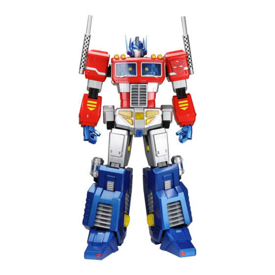
Agora Models OPTIMUS PRIME Build Instructions
Hide thumbs
Also See for OPTIMUS PRIME:
- Build instructions (50 pages) ,
- Build instructions (50 pages) ,
- Build instructions (13 pages)

Related Manuals for Agora Models OPTIMUS PRIME


Summary of Contents for Agora Models OPTIMUS PRIME
- Page 1 Pack 06 B U I L D I N S T R U C T I O N S ASSEMBLING THE FEET – PART 1 ASSEMBLING THE FEET – PART 2 ASSEMBLING THE FEET – PART 3 TRANSFORMERS and HASBRO and all related trademarks and logos are trademarks of Hasbro, Inc. ©2023 Hasbro.
- Page 2 Always protect the paint finish on components by placing a cutting mat, sheet of white paper or soft cloth on your work surface. Left and Right! When building your Optimus Prime, the left or right hand side refers to each side as viewed by Optimus Prime. Optimus Prime’s left arm is on the viewer’s right.
- Page 3 Pack 6 Parts T R A Y 1 TR-6-19 x2 TR-6-20 x2 TR-6-23 x2 TR-6-17 TR-6-18 TR-6-14 x2 TR-6-13 TR-6-12 TR-6-15 x4 TR-6-01 x2 TR-6-28 TR-6-04 x2 PB 2.3x6mm PWM 2x6mm TR-6-28 PM 3x12mm PM 3x8mm AGORAMODELS OPTIMUS PRIME...
- Page 4 Pack 6 Parts T R A Y 2 TR-6-09 TR-6-07 TR-6-05 ‘L’ TR-6-16 x3 TR-6-22 TR-6-21 TR-6-06 TR-6-02 TR-6-03 TR-6-10 AGORAMODELS OPTIMUS PRIME...
- Page 5 Pack 6 Parts T R A Y 3 TR-6-07 TR-6-09 TR-6-08 ‘R’ TR-6-22 TR-6-16 x3 TR-6-21 TR-6-06 TR-6-03 TR-6-11 TR-6-02 AGORAMODELS OPTIMUS PRIME...
-
Page 6: Testing The Electronics
Plug the battery pack supplied in Pack 1 into the circuit board TR-6-29. Plug the LED on cable TR-6-22 into part TR-6-23, then plug the socket on the other end into the 3-pin plug on the circuit board (c). TR-6-29 C (3 pin) TR-6-22 TR-6-23 AGORAMODELS OPTIMUS PRIME... - Page 7 Repeat to make two of these. TR-6-23 TR-6-17 TR-6-12 TR-6-19 PB2.3x6 TR-6-20 S T E P 2 Attach TR-6-19, 20 and 17 to TR-6-12, then attach TR-6-23 to 17. Secure the assembly together using 2x PB2.3x6 mm screws. AGORAMODELS OPTIMUS PRIME...
- Page 8 Attach A to B and secure them using 2x PWM 2x6mm screws. TR-6-13 TR-6-23 TR-6-18 TR-6-19 PB2.3x6 TR-6-20 S T E P 4 Attach TR-6-19, 20 and 18 to TR-6-13, then attach TR-6-23 to 18. Secure the assembly together using 2x PB2.3x6 mm screws. AGORAMODELS OPTIMUS PRIME...
- Page 9 Attach A to D and secure them using 2x PWM 2x6mm screws. TR-1-39 TR-6-15 TR-6-14 PB2.3x6 S T E P 6 Push 2x TR-6-15 into 14 and secure them using 2x PB2.3x6 mm screws. Repeat to make 2 of these. AGORAMODELS OPTIMUS PRIME...
- Page 10 Attach TR-6-05 to 07. Thread washers TR-6-28 onto PM3x8 screws and use them to fix the assembly together. PM3x8 TR-6-28 TR-6-21 TR-6-28 PM3x8 S T E P 2 Attach TR-6-21 to G. Thread washers TR-6-28 onto PM3x8 screws and use them to secure the assembly together. AGORAMODELS OPTIMUS PRIME...
- Page 11 PM3x8 TR-6-28 TR-6-16 TR-6-03 S T E P 4 Attach TR-6-16 and 03 to I. Thread washers TR-6-28 onto PM3x8 screws and use them to secure the assembly together. AGORAMODELS OPTIMUS PRIME...
- Page 12 Assembling the Feet – Part 2 TR-6-22 S T E P 5 Thread cable TR-6-22 through J as shown. PB2.3x6 TR-6-10 S T E P 6 Attach TR-6-10 to K and secure them using 4x PB2.3x6 mm screws. AGORAMODELS OPTIMUS PRIME...
- Page 13 TR-6-28 onto PM3x8 screws and use them to secure the assembly together. TR-6-28 TR-6-16 TR-6-02 S T E P 8 Attach assembly C (page 8) to M as shown, plugging in the cable into the socket as shown in the inset image. AGORAMODELS OPTIMUS PRIME...
- Page 14 Assembling the Feet – Part 2 PM3x8 TR-6-28 S T E P 9 Attach assembly C (page 9) to assembly N. Thread washers TR-6-28 onto PM3x8 screws and use them to secure parts in place. AGORAMODELS OPTIMUS PRIME...
- Page 15 2x PWM2x6 mm screws. Repeat to make two of these. TR-6-28 PM3x12 S T E P 2 Attach 1x assembly P to assembly O. Thread washers TR-6-28 onto PM3x12 screws and use them to secure the parts together. AGORAMODELS OPTIMUS PRIME...
- Page 16 Assembling the Feet – Part 3 L E F T F O O T R E A R V I E W L E F T F O O T F R O N T V I E W AGORAMODELS OPTIMUS PRIME...
- Page 17 Attach TR-6-08 to 07. Thread washers TR-6-28 onto PM3x8 screws and use them to fix the assembly together. TR-6-21 PM3x8 TR-6-28 TR-6-21 TR-6-28 PM3x8 S T E P 4 Attach TR-6-21 to Q. Thread washers TR-6-28 onto PM3x8 screws and use them to secure the assembly together. AGORAMODELS OPTIMUS PRIME...
- Page 18 PM3x8 screws and use them to fix the assembly together. S T E P 6 Attach TR-6-16 and 03 to S. Thread washers TR-6-28 onto PM3x8 screws and use them to secure the assembly together. PM3x8 TR-6-28 TR-6-16 TR-6-03 AGORAMODELS OPTIMUS PRIME...
- Page 19 Assembling the Feet – Part 3 S T E P 7 Thread cable TR-6-22 through T as shown. TR-6-22 S T E P 8 PB2.3x6 Attach TR-6-11 to U and secure them using 4x PB2.3x6 mm screws. TR-6-11 AGORAMODELS OPTIMUS PRIME...
- Page 20 TR-6-28 TR-6-16 TR-6-02 S T E P 1 0 Attach assembly E (page 9) to W as shown, plugging in the cable into the socket as shown in the inset image. AGORAMODELS OPTIMUS PRIME...
- Page 21 Attach assembly E (page 9) to assembly X. Thread washers TR-6-28 onto PM3x8 screws and use them to secure parts in place. S T E P 1 2 Attach the remaining assembly P (page 15) to assembly Y. Thread washers TR-6-28 onto PM3x12 screws and use them to secure the parts together. TR-6-28 PM3x12 AGORAMODELS OPTIMUS PRIME...
- Page 22 Assembling the Feet – Part 3 R I G H T F O O T R E A R V I E W R I G H T F O O T F R O N T V I E W AGORAMODELS OPTIMUS PRIME...
- Page 23 At this point, it’s a good idea to re-check the electronics: Connect the battery pack to the circuit board TR-6-29. One at a time, plug the sockets on the end of cables TR-6-22 into the 3-pin plug on the circuit board. The LEDs should light up. AGORAMODELS OPTIMUS PRIME...
Need help?
Do you have a question about the OPTIMUS PRIME and is the answer not in the manual?
Questions and answers