Advertisement
Quick Links
Advertisement

Subscribe to Our Youtube Channel
Related Manuals for TMG TMG-CP2000-RD110


Summary of Contents for TMG TMG-CP2000-RD110
- Page 1 W W W . T M G I N D U S T R I A L . C O M P 0 / 1 2 T o l l F r e e : 1 - 8 7 7 - 7 6 1 - 2 8 1 9...
-
Page 2: Main Specifications
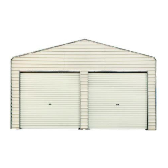
Main Specifications : Overall assembled size : W6 x H3.78 (m) / 20 x 12 (ft) Width : 6 m / 20ft Ridge peak height : 3.78 m / 12 ft Shoulder wall clearance height : 3.0 m / 10 ft ... - Page 3 TMG-CP2000-RD110 Part List Parts code Graphical Description length Short casing 198mm Lower vertical tube 2360mm Back door left tube 2360mm Back door right tube 2360mm Baseplate W150 x L200mm Metal sheet W525 x L1760mm Metal sheet W297 x L1076mm Metal sheet...
- Page 4 Edge protector 1800mm Edge protector 2360mm Edge protector 2500mm (h type) Edge protector 2020mm Edge buckle 200mm Front cross tube 1973mm Rear cross tube 1973mm Upper vertical tube 1065mm Front cross tube 1973mm Rear cross tube 1973mm Door frame cross pull 920mm tube Roll-up door...
- Page 5 Front vertical door rail L2400mm (left side) Front vertical door rail L2400mm (right side) Expansion bolt φ16x150mm Right bracket W250 x L333mm assembly Left bracket assembly W250 x L333mm Hex bolt M10x70mm Self tapping screw #12x30mm Tapping screw #12x25mm Sleeve 41mm Hole drill 85mm...
- Page 6 Installation steps Step 1 : Front truss installation Part Part W W W . T M G I N D U S T R I A L . C O M P 5 / 1 2 T o l l F r e e : 1 - 8 7 7 - 7 6 1 - 2 8 1 9...
- Page 7 Step 2 : Rear truss installation Part Part W W W . T M G I N D U S T R I A L . C O M P 6 / 1 2 T o l l F r e e : 1 - 8 7 7 - 7 6 1 - 2 8 1 9...
- Page 8 Step 3 : Install front wall panels 1. Wall panel placement order 2. When installing the wall panel, install it from top to bottom. W W W . T M G I N D U S T R I A L . C O M P 7 / 1 2 T o l l F r e e : 1 - 8 7 7 - 7 6 1 - 2 8 1 9...
- Page 9 Part Part Step 4 : Install rear wall panels 1. Wall panel placement order W W W . T M G I N D U S T R I A L . C O M P 8 / 1 2 T o l l F r e e : 1 - 8 7 7 - 7 6 1 - 2 8 1 9...
- Page 10 2. When installing the wall panel, install it from top to bottom Part Part W W W . T M G I N D U S T R I A L . C O M P 9 / 1 2 T o l l F r e e : 1 - 8 7 7 - 7 6 1 - 2 8 1 9...
- Page 11 Step 5 : Front door installation 1.Install guide rail and roll-up door. 2. After adjusting the level of the rolling door and moving up and down flexibly, install the limit block (#14C). 3. The lock pin shaft has a hole in the proper position of the guide rail. Part W W W .
- Page 12 Step 6 : Rear door installation Part W W W . T M G I N D U S T R I A L . C O M P 1 1 / 1 2 T o l l F r e e : 1 - 8 7 7 - 7 6 1 - 2 8 1 9...
-
Page 13: After The Installation
After the Installation Walk around and inspect the shelter periodically to make sure all components are still firmly secured and the whole shelter is well supported. Check all bolts and nuts as well as all connection points to make sure they are all in good position. Snow accumulating on the fabric cover must be removed as soon as possible.
Need help?
Do you have a question about the TMG-CP2000-RD110 and is the answer not in the manual?
Questions and answers