Advertisement
Quick Links
Advertisement

Subscribe to Our Youtube Channel
Related Manuals for TMG TMG-ST4061E


Summary of Contents for TMG TMG-ST4061E
- Page 1 ▶ W W W . T M G I N D U S T R I A L . C O M P 0 / 2 0 T o l l F r e e : 1 - 8 7 7 - 7 6 1 - 2 8 1 9...
-
Page 2: Main Specifications
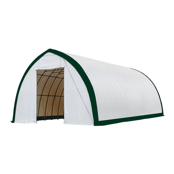
Main Specifications: - Overall assembled size : W12 x L18x H6.7 (m) / 40 x 60 x 22(ft) - Front and back roll up door : W4.08 x H4.87(m) / 13 x 16(ft) Prior to assembly Please read the instructions carefully before installation. It is important to follow your local safety regulations and industry standards during installation. - Page 3 TMG-ST4061E Part List Parts Graphical Description Length code φ58x1935mm Peak arch tube Upper rafter tube φ58x2672mm (middle truss) Upper rafter tube φ58x2672mm (front and rear truss) Sidewall tube φ58x3100mm (middle truss) Sidewall tube φ58x3100mm (front and rear truss) φ58x2067mm Lower rafter tube φ58x2067mm...
- Page 4 Door frame centre upper tube φ58x2060mm (front and rear truss) Rope pulley 30x35x130mm Rope pulley 30x35x80mm Front and rear door crossing φ58x2089mm beam (right) Front and rear door crossing φ58x2037mm beam(right) Door center vertical supporting φ42x1143mm rod for cross beam Front and rear door upper φ42x1760mm crossing tubes...
- Page 5 Steel tension cables (for #7A and front and rear W30xL800mm arches) φ30mm Water plug φ8x300m Braided rope 1 bundle φ16x150mm Expansion bolt (not included) φ32x1993mm Door dropping tube 2 groups φ32x2200mm Top cover tension tube φ32x1993mm (for both bottom sides) Top cover tension tube φ32x700mm (for both bottom sides)
- Page 6 Installation steps Step 1: Review the whole structure and choose the proper installation site Choose a solid level ground area to set up the building. Do not install in an area where the floor is soft, a wetland, cannot take the weight, or keep the building steady.
- Page 7 Parts used on this step : - (2) Left corner base plate (#6L) - (2) Right corner base plate (#6R) - (28) Middle truss base plate (#7) - (4) Door column base plate (#8) - (4) Middle column base plate (#9) - (112) Expansion bolt (#25) Figure 1 ▶...
- Page 8 Step 2 : Assemble all trusses The building includes 16 trusses : (1) Front truss (1st truss), (1) rear truss (16rd truss), and (14) middle trusses. The front and rear trusses are installed with the fabric panel (#29). Both front and rear truss include the following parts.
- Page 9 The (14) middle trusses include the following parts. Connect all tubes with bolt (#19). (refer to figure 3) Parts used on this step : - (1x14) Peak arch tube (#1) - (2x14) Upper rafter tube (#2) - (2x14) Sidewall tube (#3) - (2x14) Lower rafter tube (#4) - (1x14) Support tube for roof frame (#5A) - (2x14) Support tube for roof frame (#5B)
- Page 10 Lay down all (16) trusses on the ground as figure 4 when the assembly is all completed and before moving to next step. (refer to figure 4) Parts used on this step : - (4) Scratch resistant tape (#32) Figure 4 ▶...
- Page 11 Step 3 : Put up the front (1 ) truss Use of a crane or forklift is recommended, otherwise a team can use ropes to lift the trusses, but you have to make sure it is safe, and have enough manpower.
- Page 12 Step 4 : Put up the rest trusses Refer to Step 3 to put up the rest trusses, connect all 7 purlins (#5) with bolt (#18) and secure all bolts firmly on each span before going to next truss, include the following parts .
- Page 13 Step 5 : Tension cable installation Tension cable installation : All cables are diagonally installed on each side of the interval, total 32 cables. (refer to figure 5) - (30x2) Mounting base (#16) - (15x2) Sidewall frame steel tension cables (#17) Figure 7 ▶...
- Page 14 Step 6 : Install the remaining parts on the front and rear truss. (refer to figure 8) Parts used in this step : - (4x2) Door frame lower tube (#10) - (2x2) Door frame upper tube (#10A) - (2x2) Door frame centre upper tube (#10B) - (1x2) Front and rear door crossing beam (#12) - (1x2) Front and rear door crossing beam (#12A) - (2x2) Door center vertical supporting rod for cross beam (#12B)
- Page 15 Step 7 : Install front and rear cover panel The door cover must be zipped. Use rope (#24) to lift up the front cover (#29) from the center grommet and tie it firm to the truss tube and spread toward both sides through each grommet along the tube.
- Page 16 The rope coming out from pulley 11B must go through the upper wheel of pully 11A, then pull both ropes together slowly and start to lift the door cover. Tie both ropes to the corner base plate. Now the door cover is up. When you drop down the door cover, do not let go too quick, otherwise it might get stuck and damage the fabric.
- Page 17 Step 8 : Install the top cover (#28) Do not install the cover during windy weather! Unpack the top cover and place it along one of the long sides of the structure. Use 3 to 5 ropes to top cover (#28) pull the cover over the top of the structure, 2 or 3 people standing inside on ladders to push upwards will help to move the cover smooth without any damage.
- Page 18 Step 9 : Stretch and tighten top cover The roof cover must be stretched and tied to the front and rear truss by rope going through the flap grommets on the cover. Start from the top center and go toward both side on each end. Add or cut the rope as needed. ...
- Page 19 Step 10 : Tension the cover on the structure from both sides Insert tension tubes (#27) slowly into the bottom groove pocket on both long sides. Add the water plug (#23) on the first tension tube to avoid tearing the fabric and add one to the end of last tube (#27A) as well.
- Page 20 Step 11 : Install ratchet straps Stretch and adjust the cover from left and right, back and forth, to make sure it is square and centered. Cut the groove pocket where it aligns with ratchet (#7A), and use strap (#22) to pull tension tube (#27) toward the ratchet and secure it.
-
Page 21: After The Installation
After the Installation Walk around and inspect the shelter periodically to make sure all components are still firmly secured and the whole shelter is well supported. Check all bolts and nuts as well as all connection points to make sure they are all in good position. Check the base plates, adjust the ropes and tie downs if required and clean the cover regularly.
Need help?
Do you have a question about the TMG-ST4061E and is the answer not in the manual?
Questions and answers