Table of Contents
Advertisement
Quick Links
Advertisement
Table of Contents

Related Manuals for ZKTeco VT07-C22L


Summary of Contents for ZKTeco VT07-C22L
- Page 1 User Manual USER MANUAL VT07-C22L For TCP/IP with 2WIRE system April, 2023...
- Page 3 Remark Please follow the user manual for correct installation and testing. If there is any doubt please call our tech-supporting and customer center. Our company applies ourselves to reformation and innovation of our products. No extra notice for any change. The illustration shown here is only for reference.
-
Page 4: Table Of Contents
CATALOG Product Features ............. 1 Technical Parameters ..........1 Pictures ..............2 Operations ..............7 Security ..............8 Smart..............14 Intercom .............. 17 Message .............. 20 Setup ..............20 Web Settings ............23 System Configuration ..........25 System Diagram ............. 29 Installation .............. -
Page 5: Product Features
Security: Support 8 alarm zones with 3 states, zone and scene setup. Smart: Support smart home extension by RS485 communication(Optional). Operating system: Linux Technical Parameters Voltage: DC 48V Rated power: 7W(VT07-C22L/VT07-C23L) 8W(VT10-B21L) Standby power consumption: 3W Display screen: 7''/10.1'' Touch screen: Capacitive / Resistive touch screen Resolution: 7'': 800x480 10.1'': 1024x600... -
Page 6: Pictures
Pictures Model:VT10-B21L Speaker 10.1'' capacitive touch screen Microphone Model:VT07-C23L 7'' capacitive touch screen Speaker Handsfree Reserved Calling management center Monitoring Unlocking Microphone... - Page 7 Model:VT07-C22L(With keys) 7'' capacitive touch screen Speaker Unlocking Monitoring Calling management center Microphone Reserved Handsfree...
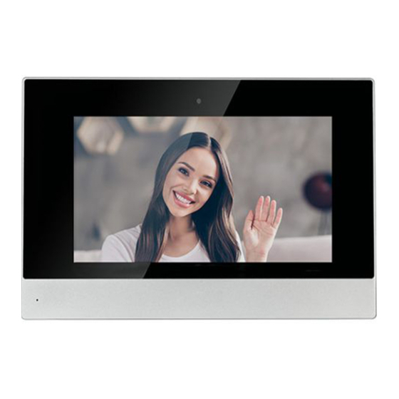
- Page 8 Model:VT07-C22L 7'' capacitive touch screen Speaker Microphone Indoor monitor doesn’t support the connection with external camera, audio ◇ extension, WIFI, Bluetooth, external USB and TF storage card. Standard indoor monitor doesn’t include RS485 communication function. ◇ Please contact the supplier if you have such requirement.
-
Page 9: Operations
Operations Main menu: Dial, Panel, Message, Security, Concierge, Monitor, Setup. Instructions of status bar and shortcut key: Call logs: Click to check call logs. Phone Book: Click to check and call contacts. SOS: Click to make a direct emergency call to Master Station. Lift control: Click to summon the elevator to go up or down. - Page 10 Dial Click “Dial” icon, the system will enter the following interface: Call Resident Input 1-3 digits building No.+ “Building” + 2-digit Unit No. + “Riser” +4-digit room No., then click icon to call. The system will enter into the following interface: When the call is answered, the system will enter into call state: If there is a camera, the caller’s image will be displayed on the screen;...
- Page 11 1.2 Call Master Station Click “ ” icon to call master station, the system will call master station No.1-No.5 successively. If the master station cannot be searched or call failed, the system will automatically call next master station. When the master station answers, it will ring and stop calling next one.
- Page 12 The door station can be monitored here. To switch the type of door station, please follow the operations as below: 1. Click ” icon to select the type of door station Click ” icon Click “ ” to start monitoring; 2.
-
Page 13: Security
Note: Indoor monitor can only receive the message sent by the management software installed on the computer which is usually located at guard center. Up to 64 records can be received in SMS. Security Click “Security” icon on the main interface, the system will enter the following interface: ON/OFF Click “ON/OFF”... - Page 14 4.1.1 ON Click “Out”, “Home”, or “Sleep” icon to activate the alarm sensors, the icon on the main interface will light up with a beep and stay lit. 4.1.2 OFF During delay time of the alarm, click “OFF” icon, the system will beep to disable the alarm.
- Page 15 4.2.2 Mode Click Mode, it will show the following interface. In this interface, you can set mode as: 3C, NO, NC or BELL. 4.2.3 Delay Time It refers to the delay time of giving an alarm. Click Delay setting, it will show the following interface with selections: 0s, 5s, 15s, 20s, 25s, 40s or 60s as the desired delay time.
-
Page 16: Setup
Scene Click “Scene” icon, the system will enter into the following interface: refers to Alarm ON, refers to Alarm OFF. To set the sensor of alarm stations, you can click the corresponding station with icon. Click "Activation Time" to select the corresponding time. The options of activation time include NONE, 30s, 40s, 60s, 100s and 300s. - Page 17 You can set the new system password with 1-16 digits (the default password is 123456). System password is used for system settings. Concierge Click “Concierge” icon on the main interface, the system will enter the following interface: Click “ ” icon to call master station, the system will call master station No.1-No.5 successively.
- Page 18 Monitor Click “Monitor” icon on the main interface, the system will enter the following interface: The IP camera can be monitored here. To switch the type of IP camera, please follow the operations as below: Click ” icon to select the camera Click ”...
- Page 19 Sounds Click “Sounds” icon, the system will enter into the following interface: “Auto Answer”, “Ring Vol”, “Intercom Vol” and "Ringtone" can be set. Date & Time Click “Date & Time” icon, the system will enter into the following interface: This interface can set “Auto”, “Date”, “Time Zone”, “12H/24H”, “Date Format”...
- Page 20 The system language can be switched. Devices Click “Devices” icon, the system will enter into the following interface: The device information can be viewed. Version Click “Version” icon, the system will enter into the following interface:...
- Page 21 Version information includnig “FW”, “UI”, “LAN IP”, “WiFi IP” and “MAC” can be viewed. More Click “More” icon, then input 1-16 digits password (the default password is 123456 ) to make the following settings: 7.7.1 Network Click “Network” icon, the system will enter into the following interface: After using the DHCP, the router will automatically distribute IP address.
- Page 22 Mask: The default Mask address is 255.255.255.0. Normally, it can keep unchanged. To modify it, click the setting box twice, a keypad will pop up for entering new Mask address. Gateway: The Gateway in one system must be in the same segment. DNS: It refers to name resolution address (DNS of local operator).
- Page 23 7.7.3 Password Click “Password” icon, the system will enter into the following interface: You can set the new system password with 1-16 digits (the default password is 123456). System password is used for system settings. 7.7.4 Reset Click “Reset” icon, the system will enter into the following interface: To confirm the operation, click OK.
-
Page 24: Web Settings
WEB SETTING Connect the indoor monitor and computer by network switch. Input the indoor monitor’s IP address in the browser, then input user name and password (the default user name is “admin”, the password is “123456") to enter into the web setting interface. Main page is used for showing firmware version and the status of SIP registration. - Page 25 2. RoomNo RoomNo page is used for setting up connection with other devices. Build: number of the building; Unit: number of the unit; Room: number of the room; Device: the numbering system for same-room number devices (Indoor Monitor 0-9; Outdoor Station 1-9); Sync: type in same numbers to make same-room number Indoor Monitors ring together;...
- Page 26 outbound server, leave it blank; User & Password: account and password of SIP;...
- Page 27 Timeout: maximum call duration; Voice Multicast: fill voice gateway to receive voice broadcast. 4. Advanced Advanced page is used for setting up accessibility features. Ex Phone: add other brand's IP Phone as SIP extension (4 devices supported); Auto Pickup: pick up automatically when receiving a call; ONU Pass: if using optical cable but not network cable in the building, it should be enabled;...
- Page 28 5. Others Others page is used for reboot. Reboot: click to reboot the device. 6. Logout Logout page is used for signing off. User Logout: click to logout the webpage. After that, you can use other accounts to login.
-
Page 29: System Configuration
System Configuration System Configuration 2 Wire Converter 2 Wire Converter 2 Wire Converter 2 Wire Converter RVV2*0.75 RVV2*0.75 Power Power adapter adapter RVV2*0.75 RVV2*0.75 RVV2*0.75 RVV2*0.75 Fiber Optical Fiber Optical 2 Wire IP Converter 2 Wire IP Converter Transceiver Transceiver Power Power RVV2*0.75... - Page 30 System Configuration System Configuration...
-
Page 33: System Diagram
System Configuration System Diagram 2 Wire RS485 Siren +12V GND 485+ 485 V+ GND Alarm +12V GND AL1 AL2 AL3 AL4 AL5 AL6 AL7 AL8 (S0/S3/S6/S8/S9) Power Power input interface (nonpolar): input power over 2-wire cable. 290A/AB 2Wire 2.RS485 Connect with smart home and alarm external module, etc. Offer a group of 12V/100mA power by RS485. - Page 34 4.Alarm interface (S0/S3/S6/S8/S9) Each interface of 8 alarm zone with 3 states can be connected with normally-open or normally-closed switch. Offer a group of 12V/100mA power by alarm interface. +12V 2.2K Normally-open sensor Alarm Normally-closed sensor...
-
Page 35: Installation
System Configuration Installation Model: VT10-B21L Built-in box Screws Size: 270*168*15mm Model: VT07-C23L Built-in box Screws Size: 235*145*19.5mm... - Page 36 Model: VT07-C22L Screws Built-in box Size: 221.4*151.4*16.5mm Installation Instructions: Suggestion During the Wall installation, the camera should be 1450 〜 1550mm above the ground. The camera tether for photographing human 400~500mm face should be the top priorit...
-
Page 37: Troubleshooting
Troubleshooting The indoor monitor cannot start up or power off automatically. Check whether it has power-failure, and power it on again. The indoor monitor display screen is too dim. Check whether the brightness and contrast settings of screen are correct. No sound during the communication. -
Page 38: Safety Instructions
Safety Instructions In order to protect you and others from harm or your device from damage, please read the following information before using the device. Do not install the device in the following places: Do not install the device in high-temperature and moist environment or the area close to magnetic field, such as the electric generator, transformer or magnet.
Need help?
Do you have a question about the VT07-C22L and is the answer not in the manual?
Questions and answers