Table of Contents
Advertisement
Quick Links
FX-PCV1617 and FX-PCV1632 VAV Box Controllers
Installation Instructions
FX-PCV1617, FX-PCV1632
Applications
The FX-PCV1617 and FX-PCV1632 are programmable
digital controllers designed for VAV box applications that
communicate by using the BACnet®
Master-Slave/Token-Passing (MS/TP) protocol. The
controllers feature an integral digital pressure sensor, a
damper actuator, and a 32-bit microprocessor. The
controllers' small package size facilitates quick field
installation and efficient use of space without
compromising high-tech control performance. The
FX-PCV controllers connect easily to either the networked
or to the non-communicating sensor for zone air
temperature sensing.
Switchable Communications
Protocols
By default, the FX-PC Family Controllers and network
sensors communicate using either the standard BACnet
protocol based on the ANSI/ASHRAE 135-2004, or the
BACnet/IP protocol.
The BACnet protocol is a standard for ANSI, ASHRAE,
and the International Standards Organization (ISO) for
building controls.
FX-PCG, FX-PCX, and FX-PCV Controllers are BTL-listed
as BACnet Application Specific Controllers (B-ASCs).
FX-PCA Field Controllers and the VMA1930 Field
Controller are BTL-listed as BACnet Advanced Application
Controllers (B-AACs). The NS Series Sensors are
BTL-listed as BACnet Smart Sensors (B-SSs).
FX-PCV1617 and FX-PCV1632 VAV Box Controllers Installation Instructions
Part No. 24-10143-489, Rev. C
Refer to the
QuickLIT website
Release 10.1 and later of the FX-PCT can be used to
switch the Field Bus communications protocol in
supported FX-PC Controllers to be either the standard
BACnet Master-Slave/Token-Passing (MS/TP) or the N2
protocol. All new controllers either use BACnet MS/TP
as the default communications protocol, or BACnet/IP.
Switchable communications protocols in the MS/TP
models provide a cost-effective upgrade and
modernization path for customers with existing N2
controllers. The Modernization Guide for Legacy N2
Controllers (LIT-12012045) and the controller-specific
documentation provide installation and commissioning
support and include tips for efficient and safe
replacement. Refer to the N2 Compatibility Options
chapter of the Controller Tool Help (LIT-12011147) for
information about mapping N2 Objects in controllers with
switchable communications protocols.
The N2-capable FX-PC Controllers can be used as
functional replacements for legacy N2 controllers. The
N2-capable FX-PC Controllers:
•
have the I/O quantities and characteristics of the
FX-PC family controllers
•
must be programmed with FX-PCT, which has
programming capabilities that are similar (but not
identical) to HVACPro, GX9100, GPL, and other
legacy tools
•
support SA Bus devices
•
support FX-WRZ wireless sensors from the controller
using the FX-WRZ7860 receiver when configured for
BACnet MS/TP communication
The N2-capable FX-PC controllers:
•
do not support Zone Bus (for example, TMZ sensors
and M100 actuators)
•
do not support passthrough in the commissioning
mode
•
do not support remote downloading or commissioning
using BACnet routing
•
do not support wireless connection to the N2 bus
Issued July 2017
for the most up-to-date version of this document.
1
Advertisement
Table of Contents
Troubleshooting

Subscribe to Our Youtube Channel
Related Manuals for Johnson Controls FX-PCV1617


Summary of Contents for Johnson Controls FX-PCV1617
- Page 1 M100 actuators) • do not support passthrough in the commissioning mode • do not support remote downloading or commissioning using BACnet routing • do not support wireless connection to the N2 bus FX-PCV1617 and FX-PCV1632 VAV Box Controllers Installation Instructions...
-
Page 2: North American Emissions Compliance
6 mm (1/4 in.) female spade terminals for input and output wiring and crimping tool or spade mounted terminal blocks • small, straight-blade screwdriver for securing wires in the terminal blocks FX-PCV1617 and FX-PCV1632 VAV Box Controllers Installation Instructions... - Page 3 If you are mounting socket. Tighten to 11 N·m , ±.5 N-m (100 lb·in, ±5 the controller to a VAV box, make sure lb·in). the screws do not interfere with damper blade movement. FX-PCV1617 and FX-PCV1632 VAV Box Controllers Installation Instructions...
- Page 4 11. Complete the mounting by rotating the damper to the full-open position. FX-PCV1617 and FX-PCV1632 VAV Box Controllers Installation Instructions...
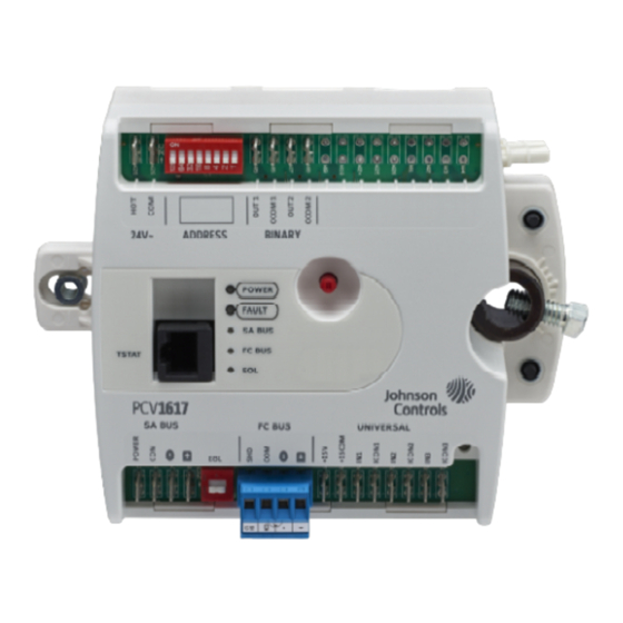
- Page 5 Figure 2: FX-PCV1617/FX-PCV1632 Controller Wiring Terminations and Physical Features FX-PCV1617 and FX-PCV1632 VAV Box Controllers Installation Instructions...
- Page 6 Table 1: FX-PCV1617/FX-PCV1632 Feature Callout Numbers and Descriptions Callout Physical Features: Description and References 24 VAC, Class 2 Supply Power Spade Terminals (see Supply Power Terminal Block) Device Address DIP Switch Block (see Setting the Device Address) Binary Outputs, 24 VAC Triacs (see Table Configurable Outputs: Voltage Analog Output (0–10 VDC) and Binary Output (24 VAC Triac)
-
Page 7: Sa Bus Spade Lugs
Wire the removable FC Bus terminal block plugs on the FX-PCV and other FX-PC controllers in a daisy-chain configuration using 3-wire twisted, shielded cable as shown in Figure 3. See Table 5 for more information. FX-PCV1617 and FX-PCV1632 VAV Box Controllers Installation Instructions... -
Page 8: Supply Power Terminal Block
Port on FX-PCV1617 and FX-PCV1632 Controllers However, when grounding the secondary of the 24 VAC transformer is required, only one connection to ground should be made near the transformer. See the following figure. Figure 8: Transformer Grounding FX-PCV1617 and FX-PCV1632 VAV Box Controllers Installation Instructions... - Page 9 Input and Output Wiring Guidelines Table 2 provides information about the functions, ratings, and requirements for the FX-PCV input and output terminals, and Table 3 provides guidelines for wire sizes and cable lengths. FX-PCV1617 and FX-PCV1632 VAV Box Controllers Installation Instructions...
- Page 10 Connects ICOMn to 24~ COM when activated. Internal Power Source: 30 VAC maximum voltage to load 0.5 A maximum output current 1.3 A at 25% duty cycle 40 mA minimum load current FX-PCV1617 and FX-PCV1632 VAV Box Controllers Installation Instructions...
- Page 11 24 AWG stranded copper 107 m 61 m (200 ft) twisted wire (350 ft) twisted wire Figure 9 to select wire Figure 9 to determine size/gauge. cable length. Use stranded copper wire. Use twisted wire cable. FX-PCV1617 and FX-PCV1632 VAV Box Controllers Installation Instructions...
-
Page 12: Termination Diagrams
Table 4: Termination Details Type of Field Device Type of Input/Output Termination Diagrams Temperature Sensor Voltage Input - External Source Voltage Input - Internal Source Voltage Input (Self-Powered) Dry Contact FX-PCV1617 and FX-PCV1632 VAV Box Controllers Installation Instructions... - Page 13 0–10 VDC Output to CO Actuator (Internal Source) Analog Output (Voltage) 24 VAC Triac Output (Switch Low, External Source) Incremental Control to Actuator (Switch Low, External Source) 24 VAC Binary Output (Switch Low, Internal Source) FX-PCV1617 and FX-PCV1632 VAV Box Controllers Installation Instructions...
- Page 14 Note: The bottom jack (J2) on the TE-700 and TE-6x00 Series Sensors is not usable as a zone bus or a connection. Network Stat with SA Bus Terminals Addressable Network Stat with SA Bus Terminals (Fixed Address = 199) FX-PCV1617 and FX-PCV1632 VAV Box Controllers Installation Instructions...
- Page 15 RJ-45 8-Position Modular Connector NA (24 AWG) 3-pair CAT 3 Cable provides +15 VDC Power for: <30.5 m (100 ft) • Wireless Commissioning Converter • VAV Balancing Tool • One-to-One Wireless Receiver • Network Sensor FX-PCV1617 and FX-PCV1632 VAV Box Controllers Installation Instructions...
-
Page 16: Setup And Adjustments
Bus, starting with device address 4. To ensure the best bus performance, set sequential device addresses with no gaps in the device address range (4, 5, 6, 7, 8, 9, and so on). The FX-PC FX-PCV1617 and FX-PCV1632 VAV Box Controllers Installation Instructions... -
Page 17: Setting The N2 Controller Address To Be Greater Than 127
EOL is active. wired field bus, the field bus is rendered inoperable until the controller Figure 11: EOL Switch Positions is disconnected or Switch 128 is set to OFF. FX-PCV1617 and FX-PCV1632 VAV Box Controllers Installation Instructions... -
Page 18: Repair Information
Troubleshooting Table 9 provides LED status indicator information for troubleshooting the FX-PCV1617 and FX-PCV1632 controllers. The following table provides some additional troubleshooting information for possible problems. Note: If you experience short circuits in the 24 VAC power supply that cause protective devices such as breakers or fuses to trip, make sure that the power connections on the FX-PCV are not reversed. -
Page 19: Troubleshooting Table
4. Reset breaker/fuse or replace transformer. Note: When replacing the transformer, it is recommended to replace with a model that utilizes a resettable circuit breaker. A circuit breaker makes solving wiring problems easier. FX-PCV1617 and FX-PCV1632 VAV Box Controllers Installation Instructions... - Page 20 Common Reference OCOM terminal is not Connect OCOM terminal of the an undesirable is incorrect. connected. configurable output to the common offset of up to 1 V. of the connected end device. FX-PCV1617 and FX-PCV1632 VAV Box Controllers Installation Instructions...
- Page 21 Replacement Barbed Fitting for use with the FX-PCV1617, FX-PCV1632, and FX-PCV1832 for Connection Tubing (Bulk Pack of 10) F-1000-326 Flexible Tubing Extension for use with the FX-PCV1617, FX-PCV1632, and FX-PCV1832, 36 cm (14 in.) Length (Bulk Pack of 20) FX-BTCVTCBL-700 Cable Replacement Set for the FX-BTCVT-1 or the FX-ATV7003-0;...
-
Page 22: Technical Specifications
Technical Specifications Table 11: FX-PCV1617 and FX-PCV1632 Controllers Product Code Numbers FX-PCV1617-0: 32-bit, Integrated VAV Controller/Actuator/Pressure Sensor—DPT, 3 UI and 2 BO, 24 VAC, FC and SA Bus, includes 8-pin TSTAT Port for use with TE-7xx Series Non-Communicating Sensors FX-PCV1617-1: 32-bit, Integrated VAV Controller/Actuator/Pressure Sensor—DPT, 3 UI and 2... - Page 23 165 x 125 x 73 mm (6.5 x 4.92 x 2.9 in.) (Height x Width x Depth) Center of Output Hub to Center of Captive Spacer: 135 mm (5-5/16 in.) Weight 0.65 kg (1.45 lb) FX-PCV1617 and FX-PCV1632 VAV Box Controllers Installation Instructions...
- Page 24 The performance specifications are nominal and conform to acceptable industry standard. For application at conditions beyond these specifications, consult the local Johnson Controls office. Johnson Controls shall not be liable for damages resulting from misapplication or misuse of its products.
Need help?
Do you have a question about the FX-PCV1617 and is the answer not in the manual?
Questions and answers