Table of Contents
Advertisement
FX70 Supervisory Controller
Installation Instructions
LP-FX7011N-0
Application
The FX70 Supervisory Controller manages networks of
field controllers using open communication protocols,
such as N2, L
W
®, and BACnet® protocols.
ON
ORKS
For information on software installation and
configuration required for a supervisory controller, refer
to the FX Workbench User's Guide (LIT-12011149).
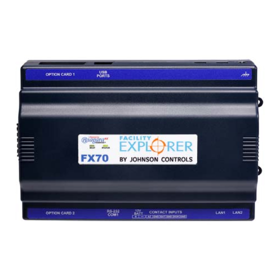
Figure 1: FX70 Supervisory Controller
North American Emissions Compliance
United States
This equipment has been tested and found to
comply with the limits for a Class A digital device
pursuant to Part 15 of the FCC Rules. These limits
are designed to provide reasonable protection
against harmful interference when this equipment is
operated in a commercial environment. This
equipment generates, uses, and can radiate radio
frequency energy and, if not installed and used in
accordance with the instruction manual, may cause
harmful interference to radio communications.
Operation of this equipment in a residential area is
likely to cause harmful interference, in which case
the user is required to correct the interference at his/
her own expense.
Canada
This Class (A) digital apparatus meets all the
requirements of the Canadian Interference-Causing
Equipment Regulations.
Cet appareil numérique de la Classe (A) respecte
toutes les exigences du Règlement sur le matériel
brouilleur du Canada.
Installation
Unpack the controller and inspect the package
contents for damaged or missing components. If
damaged, notify the appropriate carrier at once and
return any damaged components for immediate repair
or replacement.
Parts Included
Included in this package you should find the following
items:
•
An FX70 Supervisory Controller.
•
These FX70 Supervisory Controller Installation
Instructions (Part No. 24-10564-17).
•
A hardware bag containing the following items:
-
Two 6-position screw terminal plugs: one for
integral contact inputs (door tamper,
Uninterruptible Power Supply [UPS] battery
OK, and UPS AC present), and one end-mount
to wire RS-485/power to optional remote
expansion devices.
-
One 2-position screw terminal plug for external
Sealed Lead-Acid (SLA) rechargeable battery
(not provided).
-
One grounding wire, with quick-disconnect
0.187 in. (4.74 mm) female connector.
•
Power module (if ordered). The power module may
be one of the following:
-
LP-FXPM263-0 (90-263 VAC, DIN rail
mountable)
-
LP-FXPMUS-0 (90-240 VAC, with U.S. wall
adapter)
-
LP-FXPMEU-0 (90-240 VAC, with European
wall adapter)
FX70 Supervisory Controller Installation Instructions
Part No. 24-10564-17, Rev. E
Issued April 2016
1
Advertisement
Table of Contents

Related Manuals for Johnson Controls FX70


Summary of Contents for Johnson Controls FX70
- Page 1 Part No. 24-10564-17, Rev. E LP-FX7011N-0 Issued April 2016 Application Canada The FX70 Supervisory Controller manages networks of This Class (A) digital apparatus meets all the field controllers using open communication protocols, requirements of the Canadian Interference-Causing such as N2, L ®, and BACnet®...
-
Page 2: Materials And Special Tools Needed
Controller only as an operating control. Where must cut off the adapter’s barrel plug end, and then failure or malfunction of the FX70 could lead to wire leads into the controller’s end connector. A personal injury or property damage to the controlled multimeter is needed to check polarity. -
Page 3: Battery Precautions
• Mounting on a 35 mm (1.37 in.) wide DIN rail is explosion. recommended. The FX70 unit base has a molded DIN rail slot and locking clip, as does the IMPORTANT: Dispose of used battery promptly. LP-FXPM263-0 power supply module and any Keep away from children. - Page 4 DIN rail end clip (if end clip does not interfere with 6-position end connector). LP-FXPM263-0 Power Module (142) 4.1 (104) FXRIO16 3.46 (88) 11.75 (298) 15.125 (384) Figure 2: FX70 and Accessory DIN Rail Mounting Details and Dimensions, in. (mm) FX70 Supervisory Controller Installation Instructions...
-
Page 5: Tab Mounting Dimensions
DIN mounting is recommended over tab mounting. See measurements before drilling. Figure 3 and Figure 4. Figure 3: FX70 Tab Mounting Dimensions, in. (mm) Figure 4: FX70 Tab Mounting with Power Supply Attached Dimensions, in. (mm) FX70 Supervisory Controller Installation Instructions... -
Page 6: Removing And Replacing The Cover
Connector for LED Cable Board Layout Figure 6 shows the location of connectors, option slots, and other features of the main board in the FX70. For side views of communications ports and other features, LED Ribbon Cable see Figure 8. -
Page 7: Expansion Options
Figure 6: FX70 Main Board Layout Details Expansion Options Option Cards The FX70 provides for field-installable expansion using The FX70 has two available option slots to accept a these types of options: custom option card, compatible with either of these types: •... - Page 8 électrique. Tout contact avec des composants conducteurs de tensions dangereuses risque d'entraîner une décharge électrique et de provoquer des blessures graves, voire mortelles. Table 1: FX70 Supervisory Controller Option Cards Order Codes Description Number of Option Cards Allowed per Controller LP-FXRS485-0...
- Page 9 6-pin connectors that allow you to daisy-chain multiple modules together into one assembly. Table 2 lists the currently available modules. 1. Remove power from the controller, including any external battery. Table 2: Remote I/O Modules Compatible with the FX70 Supervisory Controller Model Description Notes LP-FXRIO16-0...
-
Page 10: Communications Wiring
Note: The FX70 requires FX Supervisory Software Ethernet Release 4.0 (Niagara AX 3.6 or later) for Wi-Fi support. Two, female 1-Gigabit Ethernet connections are provided on the controller. These are RJ-45 connectors Make connections to the controller in the following labeled LAN1 and LAN2. - Page 11 Ground Data set ready Request to send Clear to send not used on the FX70 RS-485 An RS-485 optically isolated port is available on three pins of the 6-position right-side connector, and always operates as COM2. As shown in Table 3, the screw terminals are minus (–), plus (+), and shield.
-
Page 12: Power Wiring
Neutral Earth Ground 120 or 240 VAC 50-60 Hz Single Phase Figure 9: FX70 Grounding and Power Wiring Connections to LP-FXPM263-0 Module Power Wiring LP-FXPM263-0 There are two power options for the controller: the The LP-FXPM263-0 module lets you power the... - Page 13 To do this, press in the four tabs on both ends of Note: I/O modules cannot be powered by the the unit, and lift the cover off. If the FX70 is plugged LP-FXPMxx-0 adapter. into the unit, you may need to slide it away to get to the cover tabs.
- Page 14 Lead Acid Backup Battery Passed Backup Battery(ies) Through 6-position Connector Figure 12: Sealed Lead-Acid (SLA) Backup Battery Connection on FX70 Note: The minimum wire size for battery connections: • 18 AWG (1.0 mm ) for up to 4 ft (1.22 m)
-
Page 15: Setup And Adjustments
FXRIO16 FXRIO16 Connect RS-485 shield wire to ground at one end only. Figure 13: Power and RS-485 Cabling Between FX70 and FXRIO16 Modules Setup and Adjustments Powerup and Initial Checkout Default Communication and Login Properties Following all mounting and wiring, perform the... -
Page 16: Operation
Shutdown occurs automatically, after data is backed up to on-board flash memory. The FX70 does not include an on/off switch. To apply power, you simply energize the AC circuit (90–263 Upon startup (boot), a test of the NiMH battery is VAC) wired to the attached LP-FXPM263-0 power performed. -
Page 17: Backup Battery
LEDs • Off — No Ethernet link is made The FX70 provides a number of LEDs on its main board, of which only the Status and Heartbeat LEDs • On — Ethernet link is present, but no activity on are visible on the cover. -
Page 18: Required Nimh Battery Maintenance
50°C or 122°F), you should only expect the battery to last approximately 1 year. The NiMH battery in the controller is fully discharged Figure 14: Replacing the FX70 NiMH Battery Pack when factory shipped. Additionally, NiMH batteries lose charge over time if not kept trickle-charged (for more 4. - Page 19 New Replacement Unit 1. Use FX Workbench to back up the FX70 To replace a faulty FX70, order a new one. To ensure configuration to your computer. proper credit for a FX70 still under warranty, contact 2. Remove power to the controller, including any the Johnson Controls Product Sales Operations Team external 12 V battery.
- Page 20 COM Slot Assignments reconnect power to them. Table 6 lists the COM slot assignments for the FX70 Controller. Table 6: COM Slot Assignments for the FX70 Supervisory Controller (Part 1 of 2) Option Slot 1 Option Slot 2 Onboard RS-232...
- Page 21 507 E. Michigan Street, Milwaukee, WI 53202 Johnson Controls® is a registered trademark of Johnson Controls, Inc. All other marks herein are the marks of their respective owners. © 2016 Johnson Controls, Inc. FX70 Supervisory Controller Installation Instructions Published in U.S.A.
Need help?
Do you have a question about the FX70 and is the answer not in the manual?
Questions and answers