ST STM32100B-EVAL User Manual
Hide thumbs
Also See for STM32100B-EVAL:
- User manual (41 pages) ,
- User manual (41 pages) ,
- User manual (45 pages)
Table of Contents
Advertisement
Quick Links
Introduction
The STM32100B-EVAL is an evaluation board for STMicroelectronics ARM
core-based STM32F100VBT6 microcontroller. It is designed as a complete development
environment with HDMI CEC, two I
8 KB internal SRAM and 128 KB internal Flash, and JTAG and SWD debugging support.
With a complete range of hardware evaluations features, the STM32100B-EVAL board is
designed to help developers evaluate all device peripherals (such as HDMI CEC, motor
control, LCD, MicroSD Card
own applications. Extension connectors make it possible to easily connect a daughterboard
or wrapping board for a specific application.
An ST-LINK is integrated on the board as an embedded in-circuit debugger and programmer
for the STM32F100VBT6 MCU.
Table 1
lists the development tools concerned by this user manual.
Table 1.
Figure 1.
September 2012
™
, serial Flash, speaker, IrDA and USART) and develop their
Applicable tools
Type
Evaluation tool
STM32F100VBT6 evaluation board (STM32100B-EVAL)
Doc ID 16533 Rev 3
STM32100B-EVAL evaluation board
2
C channels, two SPI channels, three USART channels,
UM0841
User manual
TM
Cortex-M3
Part number
STM32100B-EVAL
1/45
www.st.com
Advertisement
Table of Contents

Related Manuals for ST STM32100B-EVAL


Summary of Contents for ST STM32100B-EVAL
- Page 1 , serial Flash, speaker, IrDA and USART) and develop their own applications. Extension connectors make it possible to easily connect a daughterboard or wrapping board for a specific application. An ST-LINK is integrated on the board as an embedded in-circuit debugger and programmer for the STM32F100VBT6 MCU. Table 1 lists the development tools concerned by this user manual.
-
Page 2: Table Of Contents
Contents UM0841 Contents Overview ..........6 Features . - Page 3 ST-LINK connector CN12 ........
- Page 4 STM32100B-EVAL I/O assignments ........
- Page 5 STM32100B-EVAL IDD measurement circuit ........15...
-
Page 6: Overview
Overview UM0841 Overview Features ● Three 5 V power supply options: power jack, ST-LINK connector or daughterboard ● Boot from user Flash, system memory or SRAM ● Speaker ™ ● 1 Gbyte MicroSD Card ● 16 Mbyte serial Flash ●... -
Page 7: Hardware Layout And Configuration
UM0841 Hardware layout and configuration Hardware layout and configuration The STM32100B-EVAL board is designed around a STM32F100VBT6 microcontroller in a 100-pin LQFP package. The hardware block diagram Figure 2 shows the connections between the STM32F100VBT6 microcontroller and the peripherals (LCD, SPI Flash, USART, IrDA, speaker, HDMI CEC, temperature sensor, MicroSD Card, motor control and embedded ST- LINK). -
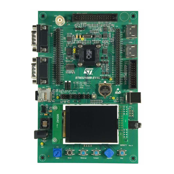
Page 8: Figure 3. Stm32100B-Eval Board Layout
Hardware layout and configuration UM0841 Figure 3. STM32100B-EVAL board layout CN4, CN5 Extension connector Motor control CN16 USART2 HDMI connector VALUELINE CN15 HDMI CN10 connector USART1 JTAG Potentiometer CN11 MicroSD CN12 ST-LINK Color LCD IrDA Audio jack Power jack Potentiometer... -
Page 9: Power Supply
Hardware layout and configuration Power supply The STM32100B-EVAL board is designed to be powered by a 5 V DC power supply and to be protected by PolyZen U10 in case of incorrect power supply configuration. It is possible to configure the evaluation board to use any of the following sources for the power supply: ●... -
Page 10: Boot Option
ST, it is not provided with board by default) or equivalent power adapter (polarity compatible with CN8) can be used to power STM32100B-EVAL board via power jack CN8 on the board. To order the recommended power supply, use the order code PSU-5C2A. -
Page 11: Clock Source
X2, 8 MHz crystal with socket for the STM32F100VBT6 microcontroller. It can be removed from the socket when the internal RC clock is used. Reset source The reset signal of the STM32100B-EVAL board is active low and the reset sources include: ● Reset button B1 ●... -
Page 12: Audio
This configuration is used for the boot loader application only. Default setting: Not fitted Audio The STM32100B-EVAL board supports playback based on a speaker on the board. This can be disabled or enabled by jumpers JP1 and JP2. The audio volume can be adjusted using the potentiometer RV1. See Section 4.4: Audio amplifier... -
Page 13: Microsd Card
2.11 Development and debug support An embedded ST-LINK STM32 JTAG interface developed by STMicroelectronic’s is available on the STM32100B-EVAL as the default debugger hardware interface. Of course, third-party debugger interfaces are also supported by the JTAG connector CN3. 2.12 Analog input One BNC connector, CN7, is connected to PA4 of the STM32F100VBT6 microcontroller as an external analog input. -
Page 14: Irda
Hardware layout and configuration UM0841 2.13 IrDA IrDA communication is supported by the IrDA transceiver U14, which is connected to USART3 of the STM32F100VBT6 microcontroller. It is enabled or disabled by jumper JP11. Table 8. IrDA jumper Jumper Description Enables/disables the IrDA transceiver. IrDA is enabled when JP11 is fitted, and disabled when JP11 is not fitted. -
Page 15: Idd Measurement
UM0841 Hardware layout and configuration 2.15 IDD measurement For IDD measurement the circuit below is implemented on the STM32100B-EVAL. Figure 4. STM32100B-EVAL IDD measurement circuit 2.15.1 Run mode In Run mode, IDD current is measured using MAX9938FEUK+ (U6) connected to the 1Ω... -
Page 16: Low Idd Measurement Improvement Procedure
2.16 HDMI CEC Two HDMI connectors CN15 and CN16 are available on the STM32100B-EVAL board. The signals CEC, SCL, SDA and HPD are supported and connected to the STM32F100VBT6 through HDMI2C1-5DIJ, the ST full integrated ESD protection, level-shifting device and signal booster for control links of the HDMI 1.3 transmitter. -
Page 17: Connectors
UM0841 Connectors Connectors Audio jack CN1 A 3.5 mm mono audio jack CN1 is available on the STM32100B-EVAL board. The speaker U12 is bypassed when earphones are plugged into CN8. JTAG debugging connector CN3 Figure 6. JTAG debugging connector CN3 (front view) -
Page 18: Daughterboard Extension Connectors Cn4 And Cn5
Daughterboard extension connectors CN4 and CN5 Two 50-pin male headers, CN4 and CN5, can connect a daughterboard or standard wrapping board to the STM32100B-EVAL board. All GPIOs are available on these connectors. The space between these two connectors and position of power, GND and RESET pin is defined as a standard (which allows to develop common daughterboards for several evaluation boards). - Page 19 Daughterboard extension connector CN4 (continued) How to disconnect from function block on Pin Description Alternate function STM32100B-EVAL board Flash_CS PD11 Disconnect STM32100B-EVAL evaluation board PD13 MC connector pin 23 from motor power drive board PD15 Disconnect STM32100B-EVAL evaluation board MC connector pin 26...
-
Page 20: Table 13. Daughterboard Extension Connector Cn5
Connectors UM0841 Table 12. Daughterboard extension connector CN4 (continued) How to disconnect from function block on Pin Description Alternate function STM32100B-EVAL board PD14 Joystick Down Remove R39 +3V3 Table 13. Daughterboard extension connector CN5 How to disconnect from component on... - Page 21 HDMI_CEC Remove R107 Temperature sensor_SCL Remove R49 Temperature sensor_INT Remove R50 Debug TDO/SWO USART2 Remove R9 Disconnect STM32100B-EVAL evaluation board MC connector pin 27 from motor power drive board. Keep JP7 on open PC11 IrDA_RX Remove R83 PA15 Debug TDI...
-
Page 22: Motor Control Connector Cn6
Connectors UM0841 Motor control connector CN6 Figure 7. Motor control connector CN6 (top view) 33 31 29 27 25 23 21 19 17 15 13 11 9 7 5 34 32 30 28 26 24 22 20 18 16 14 12 10 8 6 Table 14. -
Page 23: Analog Input Connector Cn7
Pin number Description Analog input/PA4 Power supply connector CN8 The STM32100B-EVAL board can be powered from a DC 5 V power supply via the external power supply jack (CN8) shown in Figure 9. The central pin of CN8 must be positive. -
Page 24: Rs-232 Connector Cn9 With Rts/Cts Handshake Support
Connectors UM0841 RS-232 connector CN9 with RTS/CTS handshake support Figure 10. RS-232 connector CN9 with RTS/CTS handshake support (front view) Table 16. RS-232 connector CN9 with full modem control support Pin number Description Pin number Description Connect to Pin 4 USART2_RX USART2_RTS USART2_TX... -
Page 25: Microsd Connector Cn11
Reserved SCLK/PA5 CS/PC12 Vss/GND DI/PA7 DO/PA6 8, 9 Card detect (PE7) 3.10 ST-LINK connector CN12 Figure 13. ST-LINK connector CN12 (front view) Table 19. ST-LINK USB connector (CN12) Pin number Description Pin number Description VBUS (power) Shield Shield Doc ID 16533 Rev 3... -
Page 26: St-Link Programming Connector Cn13
Connectors UM0841 3.11 ST-LINK programming connector CN13 The connector CN13 is not mounted on the board and is reserved for manufacture only. 3.12 HDMI connectors CN15 and CN16 Figure 14. HDMI connectors CN15 and CN16 Table 20. HDMI connectors (CN15 and CN16) -
Page 27: Limitations
UM0841 Limitations Limitations The MB871 board is delivered with PCB revision A or B. The PCB version is mentioned on the bottom right corner of the board. Both versions of PCB are fully compatible in configuration by default but several limitations on the PCB rev A are removed on PCB rev B. All PCB rev A limitations are explained in this chapter. -
Page 28: Schematics
Schematics UM0841 Schematics This section provides design schematics for the STM32100B-EVAL key features to help you implement these features in your own application design. This section includes: ● Figure 15: Evaluation board schematics on page 29 ● Figure 16: MCU on page 30 ●... - Page 29 JOY_DOWN Flash_CS Flash_CS JOY_LEFT JOY_LEFT SD_Flash_MOSI SD_Flash_MOSI JOY_RIGHT JOY_RIGHT SD_Flash_SCK SD_Flash_SCK JOY_UP JOY_UP SD_Flash_MISO SD_Flash_MISO Potentiometer Potentiometer TemperatureSensor_INT TemperatureSensor_INT TemperatureSensor_SDA TemperatureSensor_SDA TemperatureSensor_SCL TemperatureSensor_SCL LED1 LED1 LED2 LED2 LED3 LED3 LED4 LED4 Title: STM32100B-EVAL Number: MB871 Rev: B.1(PCB.SCH) Date: 2/10/2010 Sheet...
- Page 30 39 40 TD-0341 [RESET/Black] PA12 PA11 41 42 09.03290.01 PA10 43 44 JOY_RIGHT 45 46 JOY_LEFT 47 48 49 50 STM32F100VBT6 +3V3 +3V3 2213S-50G Bootloader_BOOT0 [N/A] 100nF BAT60J Title: RESET# Bootloader_RESET STM32100B-EVAL MCU BAT60J Number: MB871 Rev: B.1(PCB.SCH) Date: 2/11/2010 Sheet...
- Page 31 [N/A] +3V3 LED3 Close to MCU on PCB Blue LED4 User_Button User Button +3V3 TD-0341 [USER/Blue] 100nF +3V3 +3V3 TemperatureSensor_SDA TemperatureSensor_SCL Potentiometer 3386P-103H[10%] TemperatureSensor_INT OS/INT 100nF STLM75M2E Potentiometer Title: Temperature sensor STM32100B-EVAL Peripherals Number: MB871 Rev: B.1(PCB.SCH) Date: 2/2/2010 Sheet...
- Page 32 100nF T1IN T1OUT R16 0 USART1_TX T2IN T2OUT T3IN T3OUT Bootloader_RESET R1OUT R1IN R2OUT R2IN PA10 R115 USART1_RX R3OUT R3IN Bootloader_BOOT0 R4OUT R4IN R5OUT R5IN +3V3 nSHDN ST3241EBPR Title: USART1 connector STM32100B-EVAL RS232&IrDA Number: MB871 Rev: B.1(PCB.SCH) Date: 1/27/2010 Sheet...
- Page 33 Figure 19. Audio Speaker- +3V3 100pF KSS-1508 100K ST-613 3314J-1-503E Standby VOUT1 Speaker+ VIN- VOUT2 VIN+ +3V3 470nF Bypass [N/A] TS4990IST Audio_DAC Title: STM32100B-EVAL Audio Number: MB871 Rev: B.1(PCB.SCH) Date: 1/27/2010 Sheet...
- Page 34 HDMI_pin19 47151-0051 CN16 HDMI_pin1 HDMI_pin3 HDMI_pin4 HDMI_pin6 HDMI_pin7 HDMI_pin9 HDMI_pin10 HDMI_pin12 11 12 HDMI_pin13 HDMI_pin14 13 14 HDMI_pin15 HDMI_pin16 15 16 HDMI_pin18 17 18 HDMI_pin19 47151-0051 HDMI CEC Title: STM32100B-EVAL LCD & HDMI_CEC Number: MB871 Rev: B.1(PCB.SCH) Date: 1/27/2010 Sheet...
- Page 35 Figure 21. MicroSD Card and Flash +3V3 +3V3 SPI Flash 100nF HOLD Flash_CS SD_Flash_MISO M25P128-VME6G +3V3 SD_Flash_SCK SD_Flash_MOSI +3V3 +3V3 PC12 MicroSDCard_CS CN11 PJS008-2000 (SMS064FF or SMS128FF) SDcard_detect Title: STM32100B-EVAL SD&Flash Number: MB871 Rev: B.1(PCB.SCH) Date: 1/27/2010 Sheet...
- Page 36 3.3V Power +3V3 MC_PFCpwm PFC PWM 100nF MC_EnA/WAKEUP Encoder A [N/A] MC_EnB Encoder B Encoder Index 2316S-34G MC_CurrentC MC_EnIndex [N/A] [N/A] [N/A] MC_PFCsync2 MC_PFCsync1 [N/A] 10nF [N/A] [N/A] [N/A] Title: STM32100B-EVAL Motor Control MB871 B.1(PCB.SCH) Date: 1/27/2010 Number: Rev: Sheet...
- Page 37 Figure 23. JTAG and SWD debugger +3V3 [N/A] [N/A] [N/A] [N/A] PA13 TMS/SWDIO PA14 TCK/SWCLK TDO/SWO PA15 TRST RESET# RS8M22R0J1 D4 D5 [N/A] 2316S-20G +3V3 +3V3 [N/A] JTAG connector Title: STM32100B-EVAL JTAG&SWD Number: MB871 Rev: B.1(PCB.SCH) Date: 1/27/2010 Sheet...
- Page 38 VDD_1 VDD_2 VSS_2 VDD_MCU VDD_MCU VDD_3 VSS_3 VSS_1 LD1117DT33TR +3V3 Vbat VBAT VSS_4 Vout VSS_5 100nF 100nF 100nF 100nF 100nF VALUELINE QFP100 10uF 10uF 100nF VDD_MCU XCF-12 JP10 Ground U5V_ST_LINK Title: STM32100B-EVAL Power Number: MB871 Rev: B.1(PCB.SCH) Date: 2/10/2010 Sheet...
- Page 39 Figure 25. ST-LINK Spea ker- +3V3 100pF KS S -1508 JP 1 100K ST- 6 13 3314J-1-503E Sta ndby VOUT1 Spea ker+ VI N- VOUT2 VI N+ +3V3 470nF Bypass [N/A] TS4990 I ST Audio_DAC ST Microelectronics Ti tle: STM32100B - EVAL ST_LINK...
- Page 40 PD10 SD O VC I PD10 SD O SD I VC I SD I 4.7uH(1A) 4.7uF/35V 16-bit connector ST PS1 L40M 10nF 100nF 10nF Connector for 16-bit parallel application BL GND BL GND 4.7uF/10V PGND Rset FH26-51S -0.3SHW(05) CN 1...
-
Page 41: Appendix A Stm32100B-Eval I/O Assignments
UM0841 STM32100B-EVAL I/O assignments Appendix A STM32100B-EVAL I/O assignments Table 22. STM32100B-EVAL I/O assignments LQFP100 Pin name Type EVAL board I/O assignment VBAT PC13-ANTI_TAMP Anti-tamper button PC14-OSC32_IN 32K OSC PC15-OSC32_OUT I/O 32K OSC VSS_5 VDD_5 OSC_IN OSC_OUT NRST MC_ADC10 pin 26... - Page 42 STM32100B-EVAL I/O assignments UM0841 Table 22. STM32100B-EVAL I/O assignments (continued) LQFP100 Pin name Type EVAL board I/O assignment Potentiometer IDD_measure ADCin MC_TIM3_CH3 pin 27 MC_TIM3_CH4 pin 29 Boot1/ CS LCD SD card detect MC_TIM1_CH1N pin 5 MC_TIM1_CH1 pin 3 PE10...
- Page 43 UM0841 STM32100B-EVAL I/O assignments Table 22. STM32100B-EVAL I/O assignments (continued) LQFP100 Pin name Type EVAL board I/O assignment UASRT1_TX PA10 UART1 _RX PA11 LCD backlight PA12 PA13 Debug TMS VSS_2 VDD_2 PA14 Debug TCK PA15 Debug TDI PC10 IRDA TX...
-
Page 44: Revision History
Revision history UM0841 Revision history Date Revision Changes 25-Feb-2010 Initial release. 25-Feb-2010 Modified Section 2.15.3. Added “Caution” to Section 2.1. 24-Sep-2012 Replaced Figure 25: ST-LINK. Added Figure 26: 2.4 inch color LCD board. 44/45 Doc ID 16533 Rev 3... - Page 45 No license, express or implied, by estoppel or otherwise, to any intellectual property rights is granted under this document. If any part of this document refers to any third party products or services it shall not be deemed a license grant by ST for the use of such third party products or services, or any intellectual property contained therein or considered as a warranty covering the use in any manner whatsoever of such third party products or services or any intellectual property contained therein.
Need help?
Do you have a question about the STM32100B-EVAL and is the answer not in the manual?
Questions and answers