Table of Contents
Advertisement
Quick Links
MA710 (de_en)
MA000 (de_en)
Montageanleitung
Montageanleitung
PV-Kupplungsstecker PV-KST4/13II-UR
PV-Kupplungsbuchse PV-KBT4/13II-UR
Inhalt
Sicherheitshinweise ���������������������������������������������������������������������2
Erforderliches Werkzeug ............................................................. 3
Vorbereitung der Leitung ............................................................. 4
Crimpen ..................................................................................... 5
Anleitung zur Kalibrierung ........................................................... 6
Montage-Prüfung ....................................................................... 7
Stecken und Trennen der Leitungskupplung ................................8
Hinweise zur Installation ...............................................................9
Technische Daten ..................................................................... 10
Kupplungsbuchse/Female cable coupler
PV-KBT4/13II-UR
MA710 (de_en)
MA000 (de_en)
Assembly instructions
Assembly instructions
PV male cable coupler PV-KST4/13II-UR
PV female cable coupler PV-KBT4/13II-UR
Content
Safety Instructions �����������������������������������������������������������������������2
Tools required ............................................................................. 3
Cable preparation ....................................................................... 4
Crimping ..................................................................................... 5
Gaging instructions ..................................................................... 6
Assembly check ......................................................................... 7
Mating and disconnecting the cable coupler ................................8
Notes on installation ....................................................................9
Technical data .......................................................................... 10
Verschlusskappen/Sealing caps
PV-BVK4
PV-SVK4
32.0716
32.0717
Nicht im Lieferumfang/not included
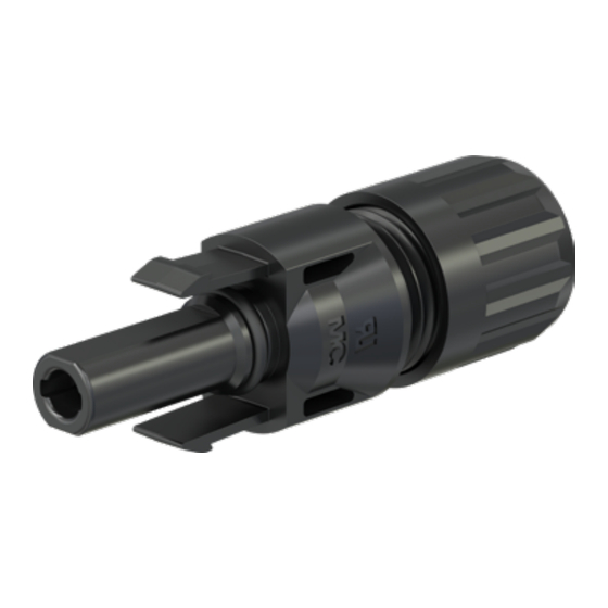
Kupplungsstecker/Male cable coupler
PV-KST4/13II-UR
1 / 12
Advertisement
Table of Contents

Subscribe to Our Youtube Channel
Related Manuals for Staubli PV-KST4/13II-UR


Summary of Contents for Staubli PV-KST4/13II-UR
-
Page 1: Table Of Contents
MA710 (de_en) MA000 (de_en) MA710 (de_en) Montageanleitung Montageanleitung Assembly instructions Assembly instructions PV-Kupplungsstecker PV-KST4/13II-UR PV male cable coupler PV-KST4/13II-UR PV-Kupplungsbuchse PV-KBT4/13II-UR PV female cable coupler PV-KBT4/13II-UR Inhalt Content Sicherheitshinweise ���������������������������������������������������������������������2 Safety Instructions �����������������������������������������������������������������������2 Erforderliches Werkzeug ............. 3 Tools required ................3 Vorbereitung der Leitung ............. -
Page 2: Sicherheitshinweise
Dokument beschrieben anwendbar werden. document. Für mehr Informationen Stäubli kontaktieren For more information, contact Stäubli • • www.staubli.com/electrical www.staubli.com/electrical Anforderungen an das Personal Requirements for personnel Die Montage und Installation dürfen ausschließlich von einer Only an electrician or electrically instructed person may assem- Elektrofachkraft oder einer elektrotechnisch unterwiesenen Per- ble, install, and commission the system. -
Page 3: Erforderliches Werkzeug
Montageschlüsselset PV-MS, Open-end spanner set PV-MS, PV-MS-PLS PV-MS Bestell-Nr. 32.6024 Order No. 32.6024 Hinweis: Note: Bedienungsanleitung MA270, Operating instructions MA270, www.staubli.com/electrical www.staubli.com/electrical (ill. 3) (ill. 3) PV-CZLX/6AWG inkl. Lokator, PV-CZLX/6AWG incl. locator, Bestell.-Nr. 32.0349 Order No. 32.0349 (ill. 4) (ill. 4) -
Page 4: Vorbereitung Der Leitung
For selection of approved cable please follow these guidelines. verwenden. Achtung: Attention: Für PV-KST4/13II-UR und PV-KBT4/13II-UR sind verzinnte For PV-KST4/13II-UR and PV-KBT4/13II-UR tinned copper oder blanke Kupferleiter zu verwenden. Bereits oxidierte or uncoated (bare) copper conductors can be used. Do not Leiter sind nicht zu verwenden. -
Page 5: Crimpen
(ill. 10) (ill. 10) Nach der Abisolierung Maß L kontrol- After stripping the cable insulation verify lieren. distance L. L = 7,5 mm to 9 mm L = 7.5 mm to 9 mm Achtung: Attention: Beim Abisolieren keine Einzeldrähte Do not cut strands when stripping abschneiden! the cable! Crimpen... -
Page 6: Anleitung Zur Kalibrierung
(ill. 15) (ill. 15) Gecrimpten Kontakt mit Kabel aus der Remove crimped contact and wire. Crimpzange entnehmen. (ill. 16) (ill. 16) Crimpung visuell kontrollieren be- Visually check the crimp according to züglich der Kriterien, die in the criteria written in IEC 60352-2:2006 + A1:2013 IEC 60352-2:2006 + A1:2013. -
Page 7: Montage-Prüfung
Montage-Prüfung Assembly check (ill. 17) (ill. 17) Angecrimpten Kontakt von hinten in die Insert the crimped contact into the Isolation bis zum Einrasten einführen. insulator of the male or female coupler Es ertönt ein „Klick“-Geräusch, sobald until engaged. dieser vollständig eingeführt ist. You will typically hear a “click”... -
Page 8: Stecken Und Trennen Der Leitungskupplung
Stecken und Trennen der Leitungskupplung Mating and disconnecting the cable coupler Stecken Mating (ill. 20) (ill. 20) Leitungskupplungen zusammenstecken Mate the cable coupler until a „Click“ bis ein „Klick“ hörbar ist. Korrektes can be heard. Check correct engage- Einrasten durch Ziehen an der Leitungs- ment by lightly pulling on the connector kupplung kontrollieren (maximum pulling force: 20 N). -
Page 9: Hinweise Zur Installation
Hinweise zur Installation Notes on installation Hinweis: Note: Wenn der Steckverbinder in Niederspannungs-Gleichstrom If the connector is to be used in low-voltage DC applications Anwendungen für andere Zwecke als in einem Photovoltaik- other than those in a photovoltaic array, please consult the infor- System verwendet werden soll, befolgen Sie bitte die Hinweise mation as provided in the Stäubli Technical Description Report. -
Page 10: Technische Daten
Technische Daten Technical data Typenbezeichnung Type designation Steckverbindersystem Connector system Ø 4 mm Bemessungsspannung Rated voltage DC 1500 V Bemessungsstrom Rated current 95 A (6AWG) Bemessungsstossspannung Rated impulse voltage 16 kV (DC 1500 V) Umgebungstemperaturbereich Ambient temperature range -40 °C...+85 °C Temperaturbereich Transport/Lagerung Transportation/storage temperature range -30 °C...+60 °C Obere Betriebstemperatur MOT max. - Page 11 11 / 12...
- Page 12 100 Market Street Stockbrunnenrain 8 Windsor, CA 95492/United States 4123 Allschwil/Switzerland Phone +1 707 838 0530 Tel. +41 61 306 55 55 +1 707 838 2474 +41 61 306 55 56 mail ec.us@staubli.com mail ec.ch@staubli.com www.staubli.com/electrical www.staubli.com/electrical 12 / 12...
Need help?
Do you have a question about the PV-KST4/13II-UR and is the answer not in the manual?
Questions and answers