Table of Contents
Advertisement
Available languages
Available languages
Quick Links
Advertisement
Table of Contents

Related Manuals for AERMEC TX24


Summary of Contents for AERMEC TX24
- Page 1 2 3 / 0 1 – 5 9 0 2 7 3 5 _ 0 1 Translation of Original instruc tions Traduc tions d’après les modes d’emploi d’origine TX24 Accessory manual · Manuel accessoire ELECTRONIC CONTROL PANEL PANNEAU DE COMMANDE ÉLECTRONIQUE...
- Page 2 Aermec S.p.A. Cher client, Nous vous remercions de vouloir en savoir plus sur un produit Aermec. Il est le résultat de plusieurs années d’expériences et d’études de conception particulières, il a été construit avec des matériaux de première sélection à l’aide de technologies très avancées.
- Page 3 All specifications are subject to change without prior notice. Although every effort has been made to ensure accuracy, Aermec shall not be held liable for any errors or omissions. Toutes les spécifications sont soumises à modifications sans préavis. Même si tous les efforts ont été faits pour assurer la précision, Aermec n'assume aucune responsabilité pour d'éventuelles erreurs ou omissions.
-
Page 4: Table Of Contents
TABLE OF CONTENTS Introduction ......................p. 5 Positioning and installation ................p. 5 Commands and visualisation ................p. 6 Luminous indications of the operating modes ...............p. 6 Electrical characteristics ..................p. 7 Using the system ....................p. 8 Dip-Switch SW1 setting ......................p. 8 Dip-Switch SW2 setting ......................p. 8 Types of system.......................p. 9 Setpoint selection ....................p. 9 Control logic...................... -
Page 5: Introduction
POSITIONING AND INSTALLATION Do not place the TX24 panel on a wall exposed to sunlight or heat from other sources. The panel must be installed in a closed and dry environment, away from possible water splashes on a flat surface. -
Page 6: Commands And Visualisation
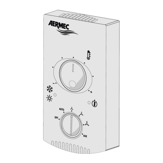
COMMANDS AND VISUALISATION Key: — (A): Speed selector; — (B): Temperature selector; — (C): Operating mode indicator light; — (D): Ventilation request indicator light. (A) Speed selector: — OFF: The fan coil is switched off. It may however start again in Heat mode (anti-freeze function) if the room temperature falls below 44,6 °F and the water temperature is suitable, in this case the red LED flashes. -
Page 7: Electrical Characteristics
ELECTRICAL CHARACTERISTICS FUNCTION Electrical characteristics M1_1 Supply control board L/AC1 Vin: 24 Vac, Imax: 5 A M1_2 Supply control board N/AC2 Vin: 24 Vac, Imax: 5 A M1_3 Control board for earth reference PE M1_4 Motor control output (V1) Voult: 24 Vac, Imax: 0.7 A M1_5 Motor control output (V2) Voult: 24 Vac, Imax: 0.7 A... -
Page 8: Using The System
USING THE SYSTEM The tab contains configuration dip switches to suit various installations. 5.1 DIP-SWITCH SW1 SETTING Dip_Board Position Meaning Shut-off valve PRESENT Dip 1 Shut-off valve ABSENT Water probe upstream from the 3-way valve Dip 2 Water probe downstream from the 3-way valve CONTINUOUS ventilation. -
Page 9: Types Of System
TYPES OF SYSTEM Key: — SA: Ambient probe — SW: Hot/Cold water probe for 2-pipe systems / Hot water probe for 4-pipe systems — SC: Cold water probe for 4-pipe systems — VS, VC, VF: Solenoid valve (Hot/Cold), Hot valve, Cold valve —... -
Page 10: Control Logic
CONTROL LOGIC The TX24 thermostat can equip the fan coils with multi-speed asynchronous motors and brushless motors. 8.1 ADJUSTMENT LOGIC There are follow options for the thermostat operating logic. 8.2 3-LEVEL THERMOSTAT The figure below shows the fan operating in Automatic mode (selector on AUTO) on the basis of the proportional error. -
Page 11: Continuous Ventilation
8.5 CONTINUOUS VENTILATION Continuous ventilation is selected by setting dip 3 ON. In this mode, ventilation continues at the selected speed even after the set temperature value has been reached. This function is disabled if the machine has no shut-off valve (dip 1 OFF);... -
Page 12: Season Changeover On The Basis Of The Water
If the thermostat uses continuous ventilation, the valve operating logic is as shown below: Heating setting Cooling setting Valve Valve Dead band 8.8 SEASON CHANGEOVER ON THE BASIS OF THE WATER If the thermostat is configured to be used without a valve (dip 1 OFF) or with a probe upstream from the valve (dip 2 ON), the measured water temperature is the one effectively available on the terminal so the season is forced to Heating or Cooling according to that temperature. -
Page 13: Environment Probe Management
9.2 ENVIRONMENT PROBE MANAGEMENT The TX24 thermostat is fitted as standard with a built-in air probe. In order to improve the possible control of the room temperature, it is possible to install an external air probe to be installed on the fan coil or in the environment. -
Page 14: Additional Checks
10 ADDITIONAL CHECKS The following fault situations are envisaged: — No water probe — No ambient probe (2 pipes) — No ambient probe (4 pipes) 10.1 NO WATER PROBE In this case, the thermostat behaves as follows: — Ventilation is always enabled —... -
Page 15: Introduction
INTRODUCTION Thermostat mural pour le contrôle des ventilo-convecteurs avec moteurs asynchrones et brushless. Le thermostat dans les installations à 2 tubes peut contrôler les ventilo-convecteurs standard ou avec un double refoulement FCZI-D (Dualjet). POSITIONNEMENT ET INSTALLATION Ne placez pas le panneau TX sur un mur exposé à la lumière du soleil ou à la chaleur d'autres sources. Le panneau doit être installé... -
Page 16: Commandes Et Visualisations
COMMANDES ET VISUALISATIONS Légende : — (A): Sélecteur de vitesse; — (B): Sélecteur de température; — (C): Voyant indiquant le mode de fonctionnement; — (D): Voyant indiquant la demande de ventilation. (A) Sélecteur de vitesse: — OFF: Le ventilo-convecteur est éteint. Il peut redémarrer en mode Chaud (fonction Antigel) si la température ambiante devient inférieure à 44,6 °F et la température d'eau est appropriée ; dans ce cas, le voyant rouge clignote. -
Page 17: Caractéristiques Électriques
CARACTÉRISTIQUES ÉLECTRIQUES FONCTION Caractéristiques électriques M1_1 Boîte à bornes L/AC1 Vin: 24 Vac, Imax: 5 A M1_2 Boîte à bornes N/AC2 Vin: 24 Vac, Imax: 5 A M1_3 Boîte à bornes pour référence de terre PE M1_4 Sortie pour commande du moteur (V1) Voult: 24 Vac, Imax: 0.7 A M1_5 Sortie pour commande du moteur (V2) -
Page 18: Utilisation Du Système
UTILISATION DU SYSTÈME a carte dispose de commutateurs DIP de configuration pour répondre aux diverses possibilités d’installation. 5.1 RÉGLAGE DIP-SWITCH SW1 Dip_Board Position Signification Vanne d’arrêt PRÉSENTE Dip 1 Vanne d’arrêt ABSENTE Sonde d’eau en amont de la vanne 3 voies Dip 2 Sonde d’eau en aval de la vanne 3 voies Ventilation CONTINUE. -
Page 19: Types D'installation
TYPES D'INSTALLATION Légende : — SA: Sonde ambiante — SW: Sonde d'eau chaud/froid pour 2 tubes - Sonde d'eau chaud pour 4 tubes — SC: Sonde d'eau froid installation à 4 tubes — VS, VC, VF: Vanne solenoïde (chaud/froid), vanne chaud, vanne froid — V3, V2, V1: Vitesse du ventilateur maximale, moyenne, minimale 2 TUBES 2 TUBES AVEC VANNE 3 VOIES 2 TUBES AVEC VANNE 2 VOIES... -
Page 20: Logiques De Contrôle
LOGIQUES DE CONTRÔLE Le thermostat TX24 pourra équiper les ventilo-convecteurs avec des moteurs asynchrones à plusieurs vitesses et des moteurs brushless. 8.1 LOGIQUES DE CONTRÔLE La logique de fonctionnement du thermostat peut être choisie entre les modes énumérés ci-dessous. 8.2 THERMOSTAT À TROIS NIVEAUX La figure indique le fonctionnement du ventilateur en mode automatique (sélecteur sur AUTO) en fonction de l’erreur proportionnelle. -
Page 21: Ventilation Continue
8.5 VENTILATION CONTINUE La sélection de la ventilation continue effectuée à l'aide du commutateur DIP 3 qui devra être réglé comme On. La ventilation continue effectue, dans la pratique, une ventilation même lorsque le thermostat est à la vitesse choisie. Cette fonction est désactivée si l'appareil n'a pas de vanne d'arrêt (commu- tateur DIP 1 OFF). -
Page 22: Changement De Saison Sur La Base De L'eau
Si le thermostat utilise la ventilation continue, la logique de fonctionnement de la vanne est celle indiquée sur la figure suivante : Point de Point de consigne chaud consigne froid Vanne Vanne Zone morte 8.8 CHANGEMENT DE SAISON SUR LA BASE DE L’EAU Si le thermostat est configuré... -
Page 23: Correction De La Sonde Ambiante
9.2 CORRECTION DE LA SONDE AMBIANTE Le thermostat TX24 intègre de série une sonde d'air. Pour améliorer l'éventuel contrôle de la température ambiante, il est possible d'installer une sonde d'air extérieur à bord du ventilo-convec- teur ou dans la pièce. -
Page 24: Commandes Supplémentaires
10 COMMANDES SUPPLÉMENTAIRES Les deux cas de panne suivants sont prévus: — Sonde d'eau absente — Sonde ambiante absente (2 tubes) — Sonde ambiante absente (4 tubes) 10.1 SONDE D'EAU ABSENTE Dans ce cas le thermostat agit comme suit: — La ventilation est toujours activée —... - Page 25 23/01 – 5902735_01...
-
Page 26: Schémas Électriques
Solenoid valve (2 pipes) · Vanne solénoïde (2 tuyaux) Solenoid valve (4 pipes) · Vanne solénoïde (4 tuyaux) Solenoid valve cold (4 pipes) · Vanne magnétique froid (4 tuyaux) Tx24 - On/Off motor · TX24 - Moteur On/Off 23/01 – 5902735_01... - Page 27 Tx24 - Inverter motor · TX24 - Moteur inverter 23/01 – 5902735_01...
- Page 28 Download the latest version · Télécharger la dernière version http://www.aermec.com/qrcode.asp?q=18388 A e r m e c S . p . A . V i a R o m a , 9 9 6 - 3 7 0 4 0 B e v i l a c q u a ( V R ) - I t a l i a T e l .
Need help?
Do you have a question about the TX24 and is the answer not in the manual?
Questions and answers