Federal Signal Corporation CommCenter D1 Series Installation And Maintenance Manual
Hide thumbs
Also See for CommCenter D1 Series:
- Installation and service instructions manual (16 pages) ,
- Installation and maintenance manual (60 pages)

Related Manuals for Federal Signal Corporation CommCenter D1 Series


Summary of Contents for Federal Signal Corporation CommCenter D1 Series
- Page 1 Model 300MB-SD CommCenter Series D1 Installation and Maintenance Manual 2561078I Rev I3 0423 Printed in U.S.A.
- Page 2 This product is subject to and covered by a limited warranty, a copy of which can be found at www.fedsig.com/SSG-Warranty. A copy of this limited warranty can also be obtained by written request to Federal Signal Corporation, 2645 Federal Signal Drive, University Park, IL 60484, email to info@fedsig.com or call +1 708-534-3400.
-
Page 3: Table Of Contents
Table of Contents Safety Message to Installers of Federal Signal Products ............5 Unpacking the Product ........................6 An Overview of the Model 300MB ....................6 Chassis Description ....................... 8 Input Configuration ......................... 8 Control Circuitry ........................9 Power Requirements ......................9 Recommendation for the Signal Lines .................. - Page 4 Tables Table 1 Kit contents ........................6 Table 2 Model 300MB Series D motherboard ................8 Table 3 Product specifications ....................10 Table 4 Replacement parts ......................23 Figures Figure 1 Dimensions and mounting holes ................... 7 Figure 2 Connections on the back of Model 300MB ..............13 Figure 3 Model AM25CK connections (balanced line) ..............
-
Page 5: Safety Message To Installers Of Federal Signal Products
Safety Message to Installers of Federal Signal Products Safety Message to Installers of Federal Signal Products People’s lives depend on your proper installation and servicing of Federal Signal products. It is important to read and follow all instructions shipped with this product. Listed below are some other important safety instructions and precautions you should follow: •... -
Page 6: Unpacking The Product
Unpacking the Product Unpacking the Product After unpacking the product, examine it for damage that may have occurred in transit. If the 300MB has been damaged, do not attempt to install or operate it. File a claim immediately with the carrier, stating the extent of the damage. Carefully check all envelopes, shipping labels, and tags before removing or discarding them. -
Page 7: Figure 1 Dimensions And Mounting Holes
An Overview of the Model 300MB Figure 1 Dimensions and mounting holes KNOCKOUT PROVISION 0.87 in (2.21 cm) DIA., 5 PLACES FIELD WIRING BLOCK FOR 120/240 V POWER CONNECTION 2.27 in 1.28 in (5.77 cm) (3.25 cm) 11.57 in 1.06 in (29.40 cm) (2.70 cm) 1.08 in... -
Page 8: Chassis Description
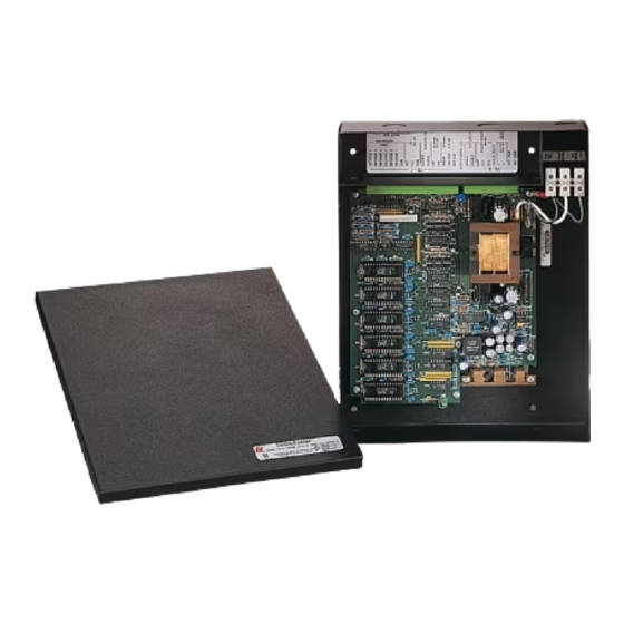
An Overview of the Model 300MB Chassis Description The CommCenter is assembled in a black, powder-coated, steel, two-piece housing. The cover is attached to the housing with four screws, two along each long edge of the enclosure. The rear of the housing incorporates two field-wiring compartments baffled off from the printed circuit board area. -
Page 9: Control Circuitry
An Overview of the Model 300MB Control Circuitry The control circuitry in the CommCenter has a built-in priority level feature. If a message is already sounding when a higher priority message is activated, the higher priority message automatically overrides the lower priority message. When the higher priority message is deactivated, the lower priority message is initiated as long as it is still activated. -
Page 10: Table 3 Product Specifications
An Overview of the Model 300MB Table 3 Product specifications Power Input Input Voltage 120/240 Vac, 50 Hz to 60 Hz; 24 Vdc Standby Current 50 mA, 120 Vac 25 mA, 240 Vac Operating Current 210 mA (max.) Power Consumption 26 W (max.) Emergency Power Source Input Input Voltage... - Page 11 An Overview of the Model 300MB Table 3 Product specifications (continued) Audio Frequency Response, Balanced Signal Line 40 Ω Max. Load, from 250 Hz to 80 kHz (Reference 1 kHz) -3 dB 40 Ω Max. Load, from 450 Hz to 60 kHz (Reference 1 kHz) -1 dB No Load, from 100 Hz to 90 kHz...
-
Page 12: Recommendation For The Signal Lines
Recommendation for the Signal Lines Recommendation for the Signal Lines REDUCED SOUND OUTPUT: If too small a diameter cable is used, unacceptable signal voltage drop in the signal line will cause reduced sound output from the remote signal device. Only use a cable having wire diameter greater than 22 AWG. -
Page 13: Connecting To Remote Devices
Connecting to Remote Devices Figure 2 Connections on the back of Model 300MB 120/240 Vac KNOCK-OUTS IN REAR OF HOUSING 10 9 8 7 6 5 4 3 2 1 17 16 15 14 13 12 11 10 9 8 7 6 5 4 3 2 1 MODEL 300MB REAR VIEW CLASS I FIELD WIRING CLASS II FIELD WIRING... -
Page 14: Unbalanced Line Application
Connecting to Remote Devices For 25 V line-operated speakers, connect them directly to the balanced signal output of the 300MB. Remove the labeled jumper from terminals TB1-13 and TB1-14 of terminal block TB1. Connect the speakers in parallel to the terminals TB1-13 and TB1-14 of terminal block TB1 on the 300MB. -
Page 15: Connecting A Low-Level Audio Output
Connecting to Remote Devices Figure 5 Cascading multiple units GROUND CASCADE IN MODEL 300MB POWER LINES 120/240 Vac MODEL 300GC PRIMARY GAIN MODEL 1716 1 5 1 4 CNTR AM25CK 120 Vac 120 Vac 120 Vac SIGNAL LINES SHIELDED TWISTED PAIR LOCAL PWR. -
Page 16: Typical Installations Of The 300Mb
Typical Installations of the 300MB Typical Installations of the 300MB This section describes four typical installations of the 300MB system. As a SelecTone Control Center In this installation, shown in Figure 6, the CommCenter is acting as a SelecTone ® control center driving a 25 V signal line. -
Page 17: Rms Speaker Line
Typical Installations of the 300MB Figure 7 Model 300MB with remote microphone and message playback GROUND MODEL 300MB 120/240 Vac CONNECTIONS TO 300MC 300MB 300VSC-1/300SCW-1 TB1-8 PTT-NO TB2-13 TB1-10 PTT-COM TB2-7 GAIN 17 16 TB1-16 SIG COM TB2-14 MIC COM CNTR TB1-17 MIC OUT... -
Page 18: Interfacing With A Central Amplified System
Typical Installations of the 300MB Interfacing with a Central Amplified System In this installation, the CommCenter is acting as an audio input to a central amplifier. Message playback can be added to an existing centrally amplified paging system. See Figure 9. Figure 9 Model 300MB with central amplifier connections GROUND MODEL 300MB... -
Page 19: Connecting Power To The Commcenter System
Connecting Power to the CommCenter System Connecting Power to the CommCenter System QUALIFIED INSTALLERS ONLY: This device is to be installed by a trained electrician who is thoroughly familiar with the National Electric Code and will follow the NEC guidelines as well as local codes. SHOCK HAZARD: Do not perform any installation or maintenance on this system when power is on. -
Page 20: Safety Messages To Maintenance Personnel
Safety Messages to Maintenance Personnel Safety Messages to Maintenance Personnel This device is to be serviced by a trained electrician who is thoroughly familiar with the National Electric Code and will follow the NEC guidelines as well as local codes. This service information is for qualified personnel only. -
Page 21: Installing Storage Chips
Installing Storage Chips Installing Storage Chips SHOCK HAZARD: Do not perform any installation or maintenance on this system when power is on. Because the 300MB-SD does not have a power switch, ensure that the power is disconnected before proceeding. Failure to heed this warning may cause serious injury or death. -
Page 22: Figure 11 Model 300Mb Motherboard
Installing Storage Chips Figure 11 Model 300MB motherboard TONE6 TONE5 TONE4 NO J9 TONE1 TONE2 TONE3 PRIORITY TONE 1 PRIORITY TONE 2 PRIORITY TONE 3 PRIORITY TONE 4 PRIORITY TONE 5 PRIORITY TONE 6 290A7316 Model 300MB-SD CommCenter Series D1 Federal Signal www.fedsig.com... -
Page 23: Getting Replacement Parts
Getting Replacement Parts Getting Replacement Parts To order replacement parts, call Customer Care. See Getting Service. Table 4 Replacement parts Description Part No Blank Message Module RMB9999SD Pre-Recorded Message Module RM1SD Getting Service IIf you are experiencing any difficulties, contact Federal Signal Customer Support at 1-800-344-4634 or 1-708-534-4756 or Technical Support at 1-800-755-7621 or 1-708-587-3587 or through e-mail at signalsupport@fedsig.com. - Page 24 2645 Federal Signal Drive University Park, Illinois 60484 www.fedsig.com Customer Support 800-548-7229 • +1 708 534-3400 Technical Support 800-524-3021 • +1 708 534-3400...
Need help?
Do you have a question about the CommCenter D1 Series and is the answer not in the manual?
Questions and answers