Federal Signal Corporation CommCenter D1 Series Installation And Service Instructions Manual
Hide thumbs
Also See for CommCenter D1 Series:
- Installation and maintenance manual (60 pages) ,
- Installation and maintenance manual (24 pages)

Related Manuals for Federal Signal Corporation CommCenter D1 Series


Summary of Contents for Federal Signal Corporation CommCenter D1 Series
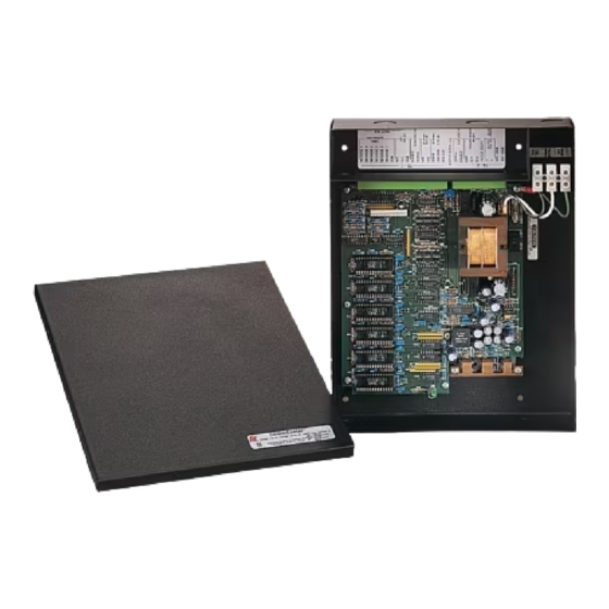
- Page 1 MODEL 300MB-SD CommCenter Series D1 INSTALLATION AND SERVICE INSTRUCTIONS 256A1078H REV H 1009 Printed in U.S.A.
- Page 2 Warranty – Seller warrants all goods for five years on parts and 2-1/2 years on labor, under the follow- ing conditions and exceptions: Seller warrants that all goods of Seller's manufacture will conform to any descriptions thereof for specifications which are expressly made a part of this sales contract and at the time of sale by Seller such goods shall be commercially free from defects in material or workman- ship.
-
Page 3: Table Of Contents
TABLE OF CONTENTS Paragraph Page SECTION I - GENERAL DESCRIPTION General ........................1-1 Chassis Description....................1-1 SECTION II - SPECIFICATIONS Power Input ......................2-1 Emergency Power Source Input ................2-1 Audio/Cascade Input ....................2-1 Audio Outputs ......................2-1 Remote Tone Activation Circuit ................2-2 Physical ........................ -
Page 4: Section I - General Description
SECTION I GENERAL DESCRIPTION 1-1. GENERAL. The CommCenter can be used for a variety of prior- itized signaling purposes, such as indicating the status The CommCenter, Model 300MB Series D, is a digi- of a machine or process, background messages, evacu- tal playback device that is capable of generating up to ation, alarm, start and dismissal, and other audible six different prerecorded voice messages, melodies, tones... - Page 5 CR10 CR11 CR13 R17 R18 CR12 TONE6 TONE5 TONE4 IC25 IC24 IC24 IC25 C119 NO J9 C127 C121 C132 TONE1 TONE2 TONE3 PRIORITY C123 R134 TONE 1 R129 C126 R136 R132 R105 C111 C106 C133 C102 C117 IC10 R106 PRIORITY C109 R125 TONE 2...
-
Page 6: Section Ii - Specifications
SECTION II SPECIFICATIONS 2-1. POWER INPUT. A. Input Voltage ................120/240 V, 50/60 Hz Standby Current ................50 mA 120 Vac Operating Current ..............210 mA (MAX) D. Power Consumption ..............26 W (MAX) 2-2. EMERGENCY POWER SOURCE INPUT. A. Input Voltage ................22–32 Vdc Standby Current ................ -
Page 7: Remote Tone Activation Circuit
2-5. REMOTE TONE ACTIVATION CIRCUIT. Message can be initiated by connecting the initiating line to CommCenter Ground by means of a dry contact or open collector. 2-6. PHYSICAL. Weight ................... Shipping 6-5/8 lb (3.01 kg) 5-1/2 lb (2.49 kg) Dimensions (HWD) ..............2.28" x 9.41" x 11.57" Operating Temperature ............... -
Page 8: Section Iii - Installation
SECTION III INSTALLATION 3-1. UNPACKING. After unpacking the Model 300MB, examine Failure to follow all safety precautions and it for damage that may have occurred in transit. If instructions may result in property damage, the equipment has been damaged, do not attempt to serious injury, or death to you or others. -
Page 9: Power
MESSAGE Jumper Marking Jumper Marking PRIORITY NO NC Failure to follow all safety precautions and TONE1 instructions may result in property damage serious injury, or death to you or others. PRIORITY NO NC TONE 2 Do not perform any installation or mainte- nance on this system when power is on. -
Page 10: Signal Lines
18 AWG to SIG HI (TB1-15) and SIG COM (TB1-16) ter- Federal Signal Corporation does not recom- minals on TB1 (see figure 3-1). Every remote Selec- mend that new or existing telephone lines be... -
Page 11: Connection To Remote Devices
GROUND CASCADE IN MODEL 300MB POWER LINES 120/240 VAC MODEL 300GC MASTER GAIN MODEL 17 16 15 CNTR 300CK TB-2 TB-1 120 VAC 120 VAC SIGNAL LINES SHIELDED TWISTED PAIR SIG. HI (YEL) LOCAL PWR. LOCAL PWR. COM. (BLU) GROUND MODEL 300MB 120/240 VAC SLAVE... -
Page 12: Typical Installations
cated at the back of the unit. Two knock-out openings 3-11. TYPICAL INSTALLATIONS. are provided. One knock-out should be removed and provided with a bushing through which the power SelecTone Installation (see figure 3-5). lines can be routed into the field wiring compartment. In this installation, the CommCenter is act- ing as a Selectone Control Center driving a 10Vrms If it is desired to use 24 VDC either as a pri-... - Page 13 GROUND MODEL 300MB 120/240 VAC GAIN 17 16 CNTR TB-2 TB-1 MODEL 300GC MODEL 300VCS-1 120 VAC MODEL 300CK 12 13 14 TB-1 TB-2 POWER LINES 120 VAC 120 VAC SIGNAL LINES SHIELDED TWISTED PAIR SIG. HI (YEL) LOCAL PWR. LOCAL PWR.
-
Page 14: Storage Chip Installation
GROUND MODEL 300MB TB1-16 SIGNAL COMMON 120/240 VAC TB1-17 MIC. OUT SIGNAL LINES SHIELDED GAIN TWISTED PAIR TO ADDITIONAL SPEAKERS, 40 OHMS MAXIMUM LOAD 17 16 CNTR TB-2 TB-1 CENTRAL AMPLIFIER AUDIO INPUT 290A2664-22B Figure 3-8. Model 300MB with Central Amplifier Connections. remote mic audio input level (16mVrms MAX.) for chip is marked with the Model Number and other the 300VSC-1. -
Page 15: Section Iv - Service
Address all communications and shipments to: Make sure to specify which series CommCenter you have before ordering any additional mes- Service Department sages. Industrial Products Federal Signal Corporation 2645 Federal Signal Drive 4-2. REPLACEMENT PARTS. University Park, IL 60466-3195 708-534-3400 Description...
Need help?
Do you have a question about the CommCenter D1 Series and is the answer not in the manual?
Questions and answers