Chapters
Table of Contents

Related Manuals for Stahl 8544/1 Series


Summary of Contents for Stahl 8544/1 Series
- Page 1 Betriebsanleitung Additional languages r-stahl.com Last- und Motorschalter, Lasttrennschalter Reihe 8544/1...
-
Page 2: Table Of Contents
Inhaltsverzeichnis Inhaltsverzeichnis Allgemeine Angaben....................3 Hersteller......................3 Zu dieser Betriebsanleitung .................3 Weitere Dokumente .....................3 Konformität zu Normen und Bestimmungen ............3 Erläuterung der Symbole ..................4 Symbole in der Betriebsanleitung ................4 Symbole am Gerät ....................4 Sicherheit ......................5 Bestimmungsgemäße Verwendung..............5 Qualifikation des Personals .................5 Restrisiken ......................6 Transport und Lagerung ..................7 Produktauswahl, Projektierung und Modifikation ..........8 Projektierung......................8... -
Page 3: Allgemeine Angaben
▶ Betriebsanleitung dem Bedien- und Wartungspersonal jederzeit zugänglich machen. ▶ Betriebsanleitung an jeden folgenden Besitzer oder Benutzer des Geräts weitergeben. ▶ Betriebsanleitung bei jeder von R. STAHL erhaltenen Ergänzung aktualisieren. ID-Nr.: 168361 / 854460300010 Publikationsnummer: 2023-02-20·BA00·III·de·10 Die Originalbetriebsanleitung ist die deutsche Ausgabe. -
Page 4: Erläuterung Der Symbole
Erläuterung der Symbole Erläuterung der Symbole Symbole in der Betriebsanleitung Symbol Bedeutung Hinweis zum leichteren Arbeiten Gefahrensituation, die bei Nichtbeachtung der GEFAHR! Sicherheitsmaßnahmen zum Tod oder zu schweren Verletzungen mit bleibenden Schäden führen kann. Gefahrensituation, die bei Nichtbeachtung der WARNUNG! Sicherheitsmaßnahmen zu schweren Verletzungen führen kann. -
Page 5: Se Fi
Normen und Bestimmungen umfasst. Für Tätigkeiten in explosionsgefährdeten Bereichen sind weitere Kenntnisse erforderlich! R. STAHL empfiehlt einen Kenntnisstand, der in folgenden Normen beschrieben wird: • IEC/EN 60079-14 (Projektierung, Auswahl und Errichtung elektrischer Anlagen) • IEC/EN 60079-17 (Prüfung und Instandhaltung elektrischer Anlagen) •... -
Page 6: Restrisiken
▶ Verpacktes Gerät nicht stapeln. ▶ Verpackung und Gerät auf Beschädigung prüfen. Beschädigungen umgehend an R. STAHL melden. Beschädigtes Gerät nicht in Betrieb nehmen. ▶ Gerät in Originalverpackung, trocken (keine Betauung) und in stabiler Lage lagern. ▶ Gerät und weitere Systemkomponenten während der Montage nicht beschädigen. -
Page 7: Gr 4 Transport Und Lagerung
▶ Gerät nicht ändern oder umbauen. ▶ Instandsetzung sowie Reparaturen am Gerät nur mit Original-Ersatzteilen und nach Absprache mit R. STAHL durchführen. 3.3.2 Verletzungsgefahr Stromschlag Während des Betriebs und der Instandhaltung liegen zeitweise hohe Spannungen am Gerät an, daher muss während der Installation das Gerät spannungsfrei geschaltet sein. -
Page 8: Produktauswahl, Projektierung Und Modifikation
Produktauswahl, Projektierung und Modifikation Produktauswahl, Projektierung und Modifikation Projektierung Gerät so aufbauen und einrichten, dass es immer innerhalb des zulässigen Temperaturbereichs betrieben wird. Um einen 6-poligen Schalter zu erreichen, können zwei 3-polige Schalter über einen Parallelantrieb verbunden werden, dabei Betriebstemperatur beachten. Bei der Projektierung neben den Sicherheitsaspekten im Kapitel 3.3.1 noch folgende Gegebenheiten berücksichtigen: ▶... - Page 9 Montage und Installation 6.1.3 Montagebohrungen anbringen Einzelschalter Die Montagebohrungen immer in Abhängigkeit vom Zentrum der Schaltwelle (Z) anbringen. Bei der Montage des Schalters auf eine plane Unterlage achten. Der Durchmesser der äußeren Bohrungen darf untereinander maximal um 0,6 mm abweichen. 23530E00 12432E00 Montagebohrungen 8544/1, 3-polig...
- Page 10 Montage und Installation Zwei Schalter mit Parallelantrieb Die Montagebohrungen immer in Abhängigkeit vom Zentrum der Schaltwelle des Parallelantriebs (Z) anbringen. Bei der Montage des Schalters auf eine plane Unterlage achten. Der Durchmesser der äußeren Bohrungen darf untereinander maximal um 0,6 mm abweichen.
- Page 11 Montage und Installation 6.1.4 Montage PE-Klemme und/oder N-Klemme (optional) Beim Schalter 8544/1, 3-polig, können optional eine PE-Klemme und/oder eine N-Klemme montiert werden. Beim Schalter 8544/1, 3-polig + N, kann optional eine PE-Klemme montiert werden. 12434E00 Montage Klemme an linker Schalterseite: ▶...
- Page 12 Montage und Installation 6.1.5 Montage Hilfskontakte (optional) GEFAHR! Explosionsgefahr durch zu geringe Luft- und Kriechstrecken! Nichtbeachten führt zu tödlichen oder schweren Verletzungen. ▶ Ex i Hilfskontakte nur mit angebrachtem Ex i Trennkörper betreiben. ▶ Kundenseitige Installation eines eigensicheren Hilfskontakts Typ 8080/1 ist nur dann zulässig, wenn an den beiden Klemmen links und rechts des verwendeten Einbauschachts keine Abgriffklemmen installiert sind.
- Page 13 Montage und Installation Demontage ▶ 15021E00 Gerät spannungsfrei schalten. ▶ Hilfskontakt-Schlüssel mit dem R. STAHL-Logo nach oben (!) zwischen Hilfskontakt und Schalterdeckel einführen. ▶ Hilfskontakt zusammen mit Hilfskontakt-Schlüssel herausziehen. ▶ Offenen Einbauschacht mit einem Ersatzschalter verschließen, damit die Kontakte nicht offen liegen.
- Page 14 Montage und Installation 6.1.6 Montage Schaltwelle(n) Die Länge der Schaltwelle ist abhängig von der Gehäusehöhe. Die Schaltwelle muss separat bestellt werden. Maßzeichnungen (alle Maße in mm [Zoll]) – Änderungen vorbehalten Größe Länge für Art. Nr. Gehäuse 8125/...2, 117,20 121,20 8544A0303-1 [2,05] 8146/...2 [4,61]...
- Page 15 Montage und Installation Zwei Schalter mit Parallelantrieb Der Parallelantrieb (Art. Nr. 171330) muss separat bestellt werden. ▶ 23995E00 Federn (2) und Schaltwellen (1) in Schalter einsetzen. Dabei Feder (2) und Schaltwelle (1) so positionieren, dass der Spannstift (3) die Schaltwelle (1) vor dem Herausnehmen schützt. ▶...
- Page 16 (siehe Abbildung). ▶ Muttern M6 (4) anziehen (Anzugsdrehmoment 4,5 Nm). 6.1.9 Montage Gehäusedeckel mit Betätigungsvorsatz ▶ Gehäusedeckel mit montiertem Betätigungsvorsatz der R. STAHL Schaltgeräte GmbH senkrecht auf Gehäuse/Welle setzen. ▶ Befestigungsschrauben des Gehäusedeckels anziehen (Anzugsdrehmoment 4,5 Nm). Last- und Motorschalter, Lasttrennschalter...
-
Page 17: Installation
Montage und Installation Installation 6.2.1 Leiteranschluss ▶ Durch eine geeignete Auswahl der verwendeten Leitungen sowie durch die Art der Verlegung sicherstellen, dass die maximal zulässigen Leitertemperaturen und die maximal zulässige Oberflächentemperatur nicht überschritten werden. ▶ Auf vorgeschriebene Querschnitte der Leiter achten. ▶... - Page 18 Montage und Installation 6.2.2 Einbaubedingungen Einbaubedingungen Luft- und Kriechstrecken Mindestabstand zum Gehäuse nach Norm EN IEC 60079-7 (Tabelle) Luftstrecke Faktor nach Norm EN IEC 60079-7 abhängig vom Leiterquerschnitt 23858E00 X * I = Mindestabstand 23859E00 23860E00 50 mm Abstand zwischen Ex e und Ex i Reihenklemmen 8 mm Abstand zwischen Ex e und Ex i Kabelleitung...
- Page 19 Montage und Installation 6.2.3 Leiteranschluss Last- und Motorschalter Zulässige Leiterquerschnitte siehe "Technische Daten". Leiteranschluss an Hauptklemme ▶ Leiter abisolieren (Abisolierlänge siehe "Technische Daten"). ▶ Leiter so in Hauptklemme einlegen, dass Leiterisolation bis an Klemme heranreicht. ▶ Befestigungsschraube der Hauptklemme anziehen (Anzugsdrehmoment siehe Kapitel "Technische Daten").
- Page 20 Montage und Installation 12441E00 ▶ Schutzfolie von Einlegeprisma (6) beidseitig abziehen und Einlegeprisma in Hauptklemme (7) einkleben. ▶ Klemmplatte (5) in Hauptklemme (7) einlegen und Befestigungsschraube der Hauptklemme (1) anziehen (Anzugsdrehmoment siehe Kapitel "Technische Daten"). ▶ Leiter mit Ringkabelschuh (4) und Federring (3) auf Schraube der Klemmplatte stecken und mit Mutter (2) festschrauben (Anzugsdrehmoment siehe Kapitel "Technische Daten").
- Page 21 Montage und Installation 6.2.5 Leiteranschluss an Abgriffklemme GEFAHR! Explosionsgefahr durch zu geringe Luft- und Kriechstrecken! Nichtbeachten führt zu schweren oder tödlichen Verletzungen. ▶ KEINE Abgriffklemmen direkt neben eigensicheren Hilfskontakten installieren. GEFAHR! Explosionsgefahr durch unbeabsichtigtes Lösen der Abgriffklemme! Nichtbeachten führt zu tödlichen oder schweren Verletzungen. ▶...
- Page 22 Montage und Installation 6.2.9 Leiteranschluss Hilfskontakte Nicht-eigensichere Hilfskontakte ▶ Leiter abisolieren (Abisolierlänge siehe "Technische Daten"). ▶ Leiter so in Klemmen einlegen, dass die Leiterisolation bis an Klemmen heranreicht. ▶ Befestigungsschrauben der Klemmen anziehen (Anzugsdrehmoment siehe Kapitel "Technische Daten"). ▶ Leiter über den Kabelkanal seitlich vom Schalter wegführen, um kreuzungsfreie Verlegung der Hilfsstromkreise zu den Hauptstromkreisen sicherzustellen.
-
Page 23: Inbetriebnahme
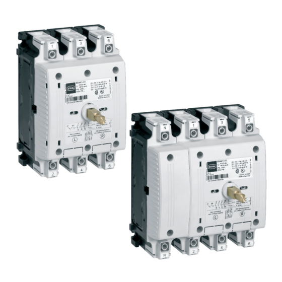
Das Gerät ist in den Varianten 8544/1-3. (3-polig) und 8544/1-4. (3-polig + N) erhältlich. Die Schalterbetätigung erfolgt ausschließlich über einen Betätigungsvorsatz der R. STAHL Schaltgeräte GmbH, der über eine Schaltwelle mit dem Schalter verbunden ist. Der Betätigungsvorsatz wird in der Gehäusewand oder im Gehäusedeckel eingebaut und kann optional mit einer Deckelverriegelung ausgestattet werden. -
Page 24: Reparatur
▶ Rücksendung bzw. Verpackung der Geräte nur in Absprache mit R. STAHL durchführen! Dazu mit der zuständigen Vertretung von R. STAHL Kontakt aufnehmen. Für die Rücksendung im Reparatur- bzw. Servicefall steht der Kundenservice von R. STAHL zur Verfügung. ▶ Kundenservice persönlich kontaktieren. -
Page 25: Anhang A
Anhang A Anhang A 14.1 Technische Daten Explosionsschutz Global (IECEx) Gas, Staub und IECEx PTB 09.0011 U Bergbau Ex db eb IIC Gb Ex db eb I Mb Europa (ATEX) Gas, Staub und PTB 08 ATEX 1060 U Bergbau E II 2 G Ex db eb IIC Gb E I M2 Ex db eb I Mb Bescheinigungen und Zertifikate Bescheinigungen... - Page 26 Anhang A Technische Daten Hilfskontakte Mögliche max. 2 Hilfskontaktblöcke Typ 8080/1 Hilfskontakte 8080/1-1: Schleichschaltglieder, 1 Ö + 1 S (Schließer öffnet > 20 ms vor Hauptkontakten) 8080/1-3: Schleichschaltglieder, 2 Ö 8080/1-4: Schleichschaltglieder, 2 S Bemessungs- 250 V AC / DC betriebsspannung 400 V AC, bei gleichem Potential beider Kontakte 500 V AC, bei 1 Ö...
- Page 27 Anhang A Technische Daten Umgebungsbedingungen Umgebungs- 8544/1-.1: -30 ... +80 °C temperatur 8544/1-.2: -50 ... +80 °C abhängig von Bemessungsbetriebsstrom und Temperaturklasse: 80 A 63 A ≤ 60 °C ≤ 60 °C ≤ 75 °C ≤ 75 °C ≤ 80 °C (Die Lagertemperatur entspricht der Umgebungstemperatur) Mechanische Daten Schutzart...
-
Page 28: Anhang B
Anzugsdrehmoment Hauptklemmen 6 ... 8 Nm Abgriffklemmen 1,5 ... 1,8 Nm Hilfskontakte 0,4 Nm Montage / Installation Einbaulage beliebig Weitere technische Daten, siehe r-stahl.com. Anhang B 15.1 Geräteaufbau 23886E00 Gerätelement Beschreibung Hilfskontaktelemente Anschluss der Hilfsfunktionen Hauptkontaktklemme Anschluss der Primärversorgung Blindabdeckung –... -
Page 29: 15.2 Maßangaben / Befestigungsmaße
Anhang B 15.2 Maßangaben / Befestigungsmaße Maßzeichnungen (alle Maße in mm [Zoll]) – Änderungen vorbehalten 5,50 5,50 12429E00 12430E00 8544/1, 3-polig 8544/1, 3-polig + N Maß A Montagesatz Schalt- Einbau in welle Gehäuse 191,7 8544A0303-3 8146/...5 [7,55] [4,37] 8125/...5 151,7 8544A0303-2 8146/...3 [5,97]... - Page 31 Operating instructions Additional languages r-stahl.com Load and motor switches, load disconnect switches Series 8544/1...
- Page 32 Contents Contents General Information .....................3 Manufacturer......................3 About these Operating Instructions..............3 Further Documents ....................3 Conformity with Standards and Regulations............3 Explanation of Symbols ..................4 Symbols used in these Operating Instructions.............4 Symbols on the Device ..................4 Safety........................5 Intended Use......................5 Personnel Qualification ..................5 Residual Risks .....................6 Transport and Storage ..................7 Product Selection, Project Engineering and Modification ........8 Project Engineering....................8...
-
Page 33: En Fr
Make the operating instructions accessible to operating and maintenance staff at all times. ▶ Pass the operating instructions on to each subsequent owner or user of the device. ▶ Update the operating instructions every time R. STAHL issues an amendment. ID no.: 168361 / 854460300010 Publication code: 2023-02-20·BA00·III·en·10... -
Page 34: Explanation Of Symbols
Explanation of Symbols Explanation of Symbols Symbols used in these Operating Instructions Symbol Meaning Handy hint for making work easier Dangerous situation which can result in fatal or severe injuries DANGER! causing permanent damage if the safety measures are not complied with. -
Page 35: Se Fi
Specialists who perform these activities must have a level of knowledge that meets applicable national standards and regulations. Additional knowledge is required for any activity in hazardous areas! R. STAHL recommends having a level of knowledge equal to that described in the following standards: •... -
Page 36: Residual Risks
▶ Do not stack packaged devices. ▶ Check the packaging and the device for damage. Report any damage to R. STAHL immediately. Do not commission a damaged device. ▶ Store the device in its original packaging in a dry place (with no condensation), and make sure that it is stable. -
Page 37: Gr 4 Transport And Storage
Do not change or modify the device. ▶ Service and repair the device only using original spare parts and after consultation with R. STAHL. 3.3.2 Risk of Injury Electric shock During operation and maintenance, the device has high voltage applied to it at times. -
Page 38: Product Selection, Project Engineering And Modification
Product Selection, Project Engineering and Modification Product Selection, Project Engineering and Modification Project Engineering Mount and install the device in such a way that it is always operated within the permissible temperature range. To produce a 6-pole switch, two 3-pole switches can be connected using a parallel drive. When doing so, note the service temperature. - Page 39 Mounting and Installation 6.1.3 Making Mounting Holes Single switch Always make the mounting holes relative to the centre of the selector shaft (Z). When mounting the switch, ensure that the mounting surface is flat. The diameters of the external drilled holes must not differ from each other by more than 0.6 mm.
- Page 40 Mounting and Installation Two switches with parallel drive Always make the mounting holes relative to the centre of the selector shaft of the parallel drive (Z). When mounting the switch, ensure that the mounting surface is flat. The diameters of the external drilled holes must not differ from each other by more than 0.6 mm.
- Page 41 Mounting and Installation 6.1.4 Mounting the PE Terminal and/or N Terminal (optional) For the 8544/1 switch with three poles, a PE terminal and/or an N terminal can optionally be installed. For the 8544/1 switch with three poles + N, a PE terminal can optionally be installed. 12434E00 Mounting the terminal on the left-hand side of the switch: ▶...
- Page 42 Mounting and Installation 6.1.5 Mounting Auxiliary Contacts (optional) DANGER! Explosion hazard due to creepage distances and clearances being too short! Non-compliance results in severe or fatal injuries. ▶ Do not operate Ex i auxiliary contacts without an attached Ex i separator. ▶...
- Page 43 Disconnect the device from the power supply. ▶ Insert the auxiliary contact key between the auxiliary contact and the switch cover with the R. STAHL logo pointing upwards (!). ▶ Remove the auxiliary contact together with auxiliary contact key. ▶...
- Page 44 Mounting and Installation 6.1.6 Mounting the Selector Shaft(s) The length of the selector shaft depends on the enclosure height. The selector shaft must be ordered separately. Dimensional drawings (all dimensions in mm [inch]) – Subject to change Size Length for Item no.
- Page 45 Mounting and Installation Two switches with parallel drive The parallel drive (item no. 171330) must be ordered separately. ▶ 23995E00 Insert the springs (2) and selector shafts (1) into the switches. While doing so, position the spring (2) and selector shaft (1) so that the dowel pin (3) protects the selector shaft (1) against removal.
- Page 46 Tighten the M6 nuts (4) (tightening torque 4.5 Nm). 6.1.9 Mounting the Enclosure Cover with Actuator ▶ Place the enclosure cover with installed actuator from R. STAHL Schaltgeräte GmbH vertically on the enclosure/shaft. ▶ Tighten the mounting screws of the enclosure cover (tightening torque 4.5 Nm).
-
Page 47: Installation
Mounting and Installation Installation 6.2.1 Conductor Connection ▶ Ensure that the maximum permissible conductor temperatures and the maximum permissible surface temperature are not exceeded by selecting suitable conductors for use and a suitable means of running them. ▶ Ensure that conductors have the specified cross sections. ▶... - Page 48 Mounting and Installation 6.2.2 Installation Conditions Installation conditions for creepage distances and clearances minimum distance from the enclosure in accordance with EN IEC 60079-7 (table) clearance factor in accordance with EN IEC 60079-7 depending on 23858E00 conductor cross-section X * I = minimum distance 23859E00 23860E00 50 mm distance between...
- Page 49 Mounting and Installation 6.2.3 Conductor Connection of Load and Motor Switch For permissible conductor cross-sections, refer to "Technical Data". Conductor connection to main terminal ▶ Strip the conductor (for the stripping length, see "Technical data"). ▶ Insert the conductor into the main terminal and make sure that the conductor insulation reaches right up to the terminal.
- Page 50 Mounting and Installation 12441E00 ▶ Remove the protective foil from both sides of the insertion prism (6) and glue the insertion prism in the main terminal (7). ▶ Insert the clamping plate (5) into the main terminal (7) and tighten the mounting screw of the main terminal (1) (for the tightening torque, see the "Technical data"...
- Page 51 Mounting and Installation 6.2.5 Conductor Connection to Pick-off Terminal Block DANGER! Explosion hazard due to creepage distances and clearances being too short! Non-compliance results in severe or fatal injuries. ▶ DO NOT installed pick-off terminal blocks directly next to intrinsically safe auxiliary contacts.
- Page 52 Mounting and Installation 6.2.9 Auxiliary Contact Conductor Connection Non-intrinsically safe auxiliary contacts ▶ Strip the conductor (for the stripping length, see "Technical data"). ▶ Insert the conductor into the terminals and make sure that the conductor insulation reaches right up to the terminals. ▶...
-
Page 53: Commissioning
The switches are actuated exclusively by means of an actuator from R. STAHL Schaltgeräte GmbH which is connected to the switch by means of a selector shaft. The actuator is installed in the enclosure wall or the enclosure cover and can optionally be equipped with a cover lock. -
Page 54: Repair
Returning the Device ▶ Only return or package the devices after consulting R. STAHL! Contact the responsible representative from R. STAHL. R. STAHL's customer service is available to handle returns if repair or service is required. ▶ Contact customer service personally. ▶... -
Page 55: Cn 14.1 Technical Data
Appendix A Appendix A 14.1 Technical Data Explosion protection Global (IECEx) Gas, dust and mining IECEx PTB 09.0011 U Ex db eb IIC Gb Ex db eb I Mb Europe (ATEX) Gas, dust and mining PTB 08 ATEX 1060 U E II 2 G Ex db eb IIC Gb E I M2 Ex db eb I Mb Certifications and certificates... - Page 56 Appendix A Technical data Auxiliary contacts Possible auxiliary max. 2 auxiliary contact blocks, type 8080/1 contacts 8080/1-1: Slow-action contacts, 1 NC + 1 NO (NO opens > 20 ms before main contacts) 8080/1-3: Slow-action contacts, 2 NC 8080/1-4: Slow-action contacts, 2 NO Rated operational 250 V AC/DC voltage...
- Page 57 Appendix A Technical data Ambient conditions Ambient temperature 8544/1-.1: -30 to +80 °C 8544/1-.2: -50 to +80 °C depending on rated operational current and temperature class: 80 A 63 A ≤ 60 °C ≤ 60 °C ≤ 75 °C ≤ 75 °C ≤...
-
Page 58: 15.1 Device Design
6 to 8 Nm Pick-off terminal 1.5 to 1.8 Nm blocks Auxiliary contacts 0.4 Nm Mounting/installation Mounting orientation For further technical data, see r-stahl.com. Appendix B 15.1 Device Design 23886E00 Device element Description Auxiliary contact elements Connection of the auxiliary functions... -
Page 59: 15.2 Dimensions/Fastening Dimensions
Appendix B 15.2 Dimensions/Fastening Dimensions Dimensional drawings (all dimensions in mm [inch]) – Subject to change 5,50 5,50 12429E00 12430E00 8544/1, 3-pole 8544/1, 3-pole + N Dimen- Assembly kit Selec- Installa- sion A tor shaft tion in enclosure 191.7 8544A0303-3 8146/...5 [7.55] [4.37]...
Need help?
Do you have a question about the 8544/1 Series and is the answer not in the manual?
Questions and answers