Stahl 8006/4 Series Operating Instructions Manual
Load and motor switch/control switch
Hide thumbs
Also See for 8006/4 Series:
- Operating instructions manual (29 pages) ,
- Operating instructions manual (33 pages)
Chapters
Table of Contents

Related Manuals for Stahl 8006/4 Series


Summary of Contents for Stahl 8006/4 Series
- Page 1 Betriebsanleitung Additional languages r-stahl.com Last- und Motorschalter / Steuerschalter Reihe 8006/4...
-
Page 2: Table Of Contents
Inhaltsverzeichnis Inhaltsverzeichnis Allgemeine Angaben....................3 Hersteller......................3 Zu dieser Betriebsanleitung .................3 Weitere Dokumente .....................3 Konformität zu Normen und Bestimmungen ............3 Erläuterung der Symbole ..................4 Symbole in der Betriebsanleitung ................4 Symbole am Gerät ....................4 Sicherheit ......................5 Bestimmungsgemäße Verwendung..............5 Qualifikation des Personals .................5 Restrisiken ......................6 Transport und Lagerung ..................7 Produktauswahl, Projektierung und Modifikation ..........7 Projektierung......................7... -
Page 3: Allgemeine Angaben
▶ Betriebsanleitung dem Bedien- und Wartungspersonal jederzeit zugänglich machen. ▶ Betriebsanleitung an jeden folgenden Besitzer oder Benutzer des Geräts weitergeben. ▶ Betriebsanleitung bei jeder von R. STAHL erhaltenen Ergänzung aktualisieren. ID-Nr.: 200128 / 8006603300 Publikationsnummer: 2021-10-27·BA00·III·de·10 Die Originalbetriebsanleitung ist die deutsche Ausgabe. -
Page 4: Erläuterung Der Symbole
Erläuterung der Symbole Erläuterung der Symbole Symbole in der Betriebsanleitung Symbol Bedeutung Hinweis zum leichteren Arbeiten Gefahrensituation, die bei Nichtbeachtung der GEFAHR! Sicherheitsmaßnahmen zum Tod oder zu schweren Verletzungen mit bleibenden Schäden führen kann. Gefahrensituation, die bei Nichtbeachtung der WARNUNG! Sicherheitsmaßnahmen zu schweren Verletzungen führen kann. -
Page 5: Se Fi
Normen und Bestimmungen umfasst. Für Tätigkeiten in explosionsgefährdeten Bereichen sind weitere Kenntnisse erforderlich! R. STAHL empfiehlt einen Kenntnisstand, der in folgenden Normen beschrieben wird: • IEC/EN 60079-14 (Projektierung, Auswahl und Errichtung elektrischer Anlagen) • IEC/EN 60079-17 (Prüfung und Instandhaltung elektrischer Anlagen) •... -
Page 6: Restrisiken
▶ Gerät nicht belasten. ▶ Verpackung und Gerät auf Beschädigung prüfen. Beschädigungen umgehend an R. STAHL melden. Beschädigtes Gerät nicht in Betrieb nehmen. ▶ Gerät in Originalverpackung, trocken (keine Betauung), in stabiler Lage und sicher vor Erschütterungen lagern. Übermäßige Erwärmung oder elektrostatische Aufladung Durch eine fehlerhafte Einrichtung im Schaltschrank, durch den Betrieb außerhalb... -
Page 7: Gr 4 Transport Und Lagerung
Beschädigungen prüfen lassen. Schalter in diesem Fall außer Betrieb nehmen. ▶ Instandsetzung sowie Reparaturen am Gerät nur mit Original-Ersatzteilen und nach Absprache mit R. STAHL durchführen. Transport und Lagerung ▶ Gerät sorgfältig und unter Beachtung der Sicherheitshinweise (siehe Kapitel "Sicherheit") transportieren und lagern. -
Page 8: Installation
Montage und Installation 6.1.2 Montage der Abdeckungen 15088E00 IP20-Abdeckung: ▶ IP20-Abdeckung (1) auf den Kontakt rasten. Bezeichnungsschild (4) in die Nut der IP20-Abdeckung (1) stecken. Ex i-Abdeckung: ▶ Ex i-Abdeckung (3) auf den Kontakt rasten. Ex i-Deckel (2) in die Ex i-Abdeckung (3) rasten. - Page 9 Montage und Installation 10,5 14288E00 Anschlussart Anschlussklemmen Anschlussquerschnitt eindrähtig / 1,5 ... 6,0 mm (10 mm eindrähtig) feindrähtig Es können 1 oder 2 Leiter unter eine Anschlussklemme installiert werden. Beide Leiter müssen den gleichen Querschnitt aufweisen sowie aus dem gleichen Material bestehen.
-
Page 10: Inbetriebnahme
▶ Gerät gemäß den geltenden nationalen Bestimmungen und den Sicherheitshinweisen dieser Betriebsanleitung (Kapitel "Sicherheit") warten. Reparatur ▶ Reparaturen am Gerät nur mit Original-Ersatzteilen und nach Absprache mit R. STAHL durchführen. Last- und Motorschalter / Steuerschalter 200128 / 8006603300 Reihe 8006/4... -
Page 11: Rücksendung
▶ Rücksendung bzw. Verpackung der Geräte nur in Absprache mit R. STAHL durchführen! Dazu mit der zuständigen Vertretung von R. STAHL Kontakt aufnehmen. Für die Rücksendung im Reparatur- bzw. Servicefall steht der Kundenservice von R. STAHL zur Verfügung. ▶ Kundenservice persönlich kontaktieren. -
Page 12: Anhang A
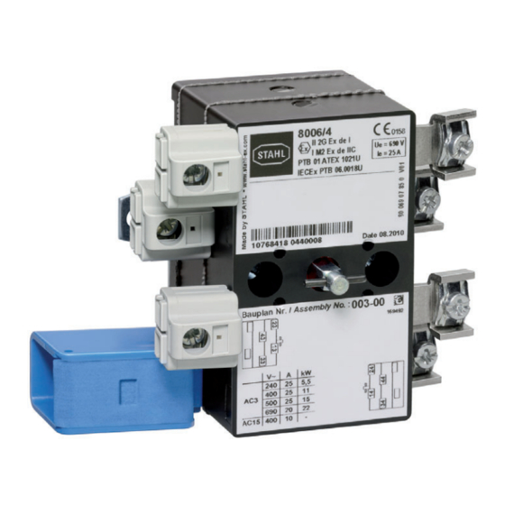
Anhang A Anhang A 14.1 Technische Daten Explosionsschutz Global (IECEx) IECEx PTB 06.0018U Ex db eb ia IIC Gb Ex db eb ia I Mb Europa (ATEX) PTB 01 ATEX 1021 U E II 2 G Ex db eb ia IIC Gb E I M 2 Ex db eb ia I Mb Bescheinigungen und Zertifikate Bescheinigungen... - Page 13 Silber-Zinnoxid, Silber-Zinnoxid vergoldet (nur bei Typ 8006/4-...-08) Anschlussquerschnitt Anschluss- 1,5 ... 6 mm fein- / eindrähtig klemmen 10 mm eindrähtig Weitere Informationen siehe Kapitel 6.2.1 Verschmutzungsgrad 3 Weitere technische Daten, siehe r-stahl.com. 200128 / 8006603300 Last- und Motorschalter / Steuerschalter 2021-10-27·BA00·III·de·10 Reihe 8006/4...
-
Page 14: Anhang B
Anhang B Anhang B 15.1 Geräteaufbau 15088E00 Gerätelement Beschreibung IP20-Abdeckung Schutz vor festen Fremdkörpern, Wasser und Feuchtigkeit Ex i-Deckel Schutz der Kontakte und Leitungen Ex i-Abdeckung Schutz der Kontakte und Leitungen Bezeichnungsschild Beschriftung der Abdeckungen Last- und Motorschalter / Steuerschalter 200128 / 8006603300 Reihe 8006/4 2021-10-27·BA00·III·de·10... -
Page 15: 15.2 Maßangaben / Befestigungsmaße
Anhang B 15.2 Maßangaben / Befestigungsmaße Maßzeichnungen (alle Maße in mm [Zoll]) – Änderungen vorbehalten Schalt- ø [ø 0,2 ] 0 kammer- ø 2 x 16 [ø 0,08 x 0,63] 5, [ 0,2 ] ebenen 44 [1,73] 52 [2,05] 56 [2,20] 64 [2,52] 72 [2,83] 76 [2,99]... - Page 17 Operating instructions Additional languages r-stahl.com Load and motor switch/ control switch Series 8006/4...
- Page 18 Contents Contents General Information .....................3 Manufacturer......................3 About these Operating Instructions..............3 Further Documents ....................3 Conformity with Standards and Regulations............3 Explanation of Symbols ..................4 Symbols used in these Operating Instructions.............4 Symbols on the Device ..................4 Safety........................5 Intended Use......................5 Personnel Qualification ..................5 Residual Risks .....................6 Transport and Storage ..................7 Product Selection, Project Engineering and Modification ........7 Project Engineering....................7...
-
Page 19: General Information
Make the operating instructions accessible to operating and maintenance staff at all times. ▶ Pass the operating instructions on to each subsequent owner or user of the device. ▶ Update the operating instructions every time R. STAHL issues an amendment. ID no.: 200128 / 8006603300 Publication code: 2021-10-27·BA00·III·en·10... -
Page 20: Explanation Of Symbols
Explanation of Symbols Explanation of Symbols Symbols used in these Operating Instructions Symbol Meaning Handy hint for making work easier Dangerous situation which can result in fatal or severe injuries DANGER! causing permanent damage if the safety measures are not complied with. -
Page 21: Se Fi
Specialists who perform these activities must have a level of knowledge that meets applicable national standards and regulations. Additional knowledge is required for any activity in hazardous areas! R. STAHL recommends having a level of knowledge equal to that described in the following standards: •... -
Page 22: Residual Risks
▶ Do not place any loads on the device. ▶ Check the packaging and the device for damage. Report any damage to R. STAHL immediately. Do not commission a damaged device. ▶ Store the device in its original packaging in a dry place (with no condensation), and make sure that it is stable and protected against the effects of vibrations and knocks. -
Page 23: Gr 4 Transport And Storage
Decommission the switches in this case. ▶ Service and repair the device only using original spare parts and after consultation with R. STAHL. Transport and Storage ▶ Transport and store the device carefully and only in accordance with the safety information (see "Safety"... -
Page 24: Installation
Mounting and Installation 6.1.2 Mounting the Coverings 15088E00 IP20 cover: ▶ Snap the IP20 cover (1) onto the contact. Insert the designation plate (4) into the groove of the IP20 cover (1). Ex i cover: ▶ Snap the Ex i cover (3) onto the contact. Snap the Ex i lid (2) into the Ex i cover (3). Insert the designation plate (4) into the groove of the Ex i lid (2). - Page 25 Mounting and Installation 10,5 14288E00 Connection type Connection terminals Connection cross-section Solid/finely 1.5 to 6.0 mm (10 mm solid) stranded One or two conductors can be installed under one connection terminal. Both conductors must have the same cross-section and must be made of the same material.
-
Page 26: Commissioning
Perform overhaul of the device according to the applicable national regulations and the safety notes in these operating instructions ("Safety" chapter). Repairs ▶ Perform repairs to the device only with original spare parts and after consultation with R. STAHL. Load and motor switch/ 200128 / 8006603300 control switch 2021-10-27·BA00·III·en·10... -
Page 27: Returning The Device
Returning the Device ▶ Only return or package the devices after consulting R. STAHL! Contact the responsible representative from R. STAHL. R. STAHL's customer service is available to handle returns if repair or service is required. ▶ Contact customer service personally. ▶... - Page 28 Appendix A Appendix A 14.1 Technical Data Explosion protection Global (IECEx) IECEx PTB 06.0018U Ex db eb ia IIC Gb Ex db eb ia I Mb Europe (ATEX) PTB 01 ATEX 1021 U E II 2 G Ex db eb ia IIC Gb E I M 2 Ex db eb ia I Mb Certifications and certificates Certifications...
-
Page 29: Cn 14.1 Technical Data
Connection cross-section Connection 1.5 to 6 mm finely stranded/solid terminals 10 mm solid See chapter 6.2.1 for further information Degree of pollution For further technical data, see r-stahl.com. 200128 / 8006603300 Load and motor switch/ 2021-10-27·BA00·III·en·10 control switch Series 8006/4... -
Page 30: 15.1 Device Design
Appendix B Appendix B 15.1 Device Design 15088E00 Device element Description IP20 covering Protection against solid foreign objects, water and moisture Ex i cover Protection for contacts and conductors Ex i covering Protection for contacts and conductors Designation plate Labelling on coverings Load and motor switch/ 200128 / 8006603300 control switch... -
Page 31: 15.2 Dimensions/Fastening Dimensions
Appendix B 15.2 Dimensions/Fastening Dimensions Dimensional drawings (all dimensions in mm [inch]) – Subject to change Switching ø [ø 0,2 ] 0 chamber ø 2 x 16 [ø 0,08 x 0,63] 5, [ 0,2 ] levels 44 [1.73] 52 [2.05] 56 [2.20] 64 [2.52] 72 [2.83]...
Need help?
Do you have a question about the 8006/4 Series and is the answer not in the manual?
Questions and answers