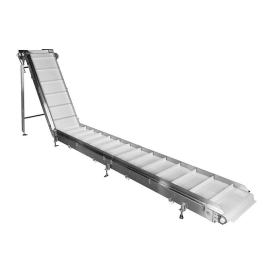
Dorner AquaGard 7350 Series Installation, Maintenance & Parts Manual
Support stands
Hide thumbs
Also See for AquaGard 7350 Series:
- Installation, maintenance, and parts manual (78 pages) ,
- Installation, maintenance & parts manual (20 pages) ,
- Installation, maintenance, and parts manual (36 pages)
Table of Contents
Advertisement
Quick Links
7350 Series Support Stands
Installation, Maintenance & Parts Manual
DORNER MFG. CORP.
P.O. Box 20 • 975 Cottonwood Ave.
Hartland, WI 53029-0020 USA
851-683 Rev. B
For other service manuals visit our website at:
www.dorner.com/service_manuals.asp
INSIDE THE USA
TEL: 1-800-397-8664
FAX: 1-800-369-2440
OUTSIDE THE USA
TEL: 262-367-7600
FAX: 262-367-5827
Advertisement
Table of Contents

Summary of Contents for Dorner AquaGard 7350 Series
- Page 1 7350 Series Support Stands Installation, Maintenance & Parts Manual DORNER MFG. CORP. INSIDE THE USA OUTSIDE THE USA P.O. Box 20 • 975 Cottonwood Ave. TEL: 1-800-397-8664 TEL: 262-367-7600 Hartland, WI 53029-0020 USA FAX: 1-800-369-2440 FAX: 262-367-5827 For other service manuals visit our website at: www.dorner.com/service_manuals.asp...
-
Page 2: Table Of Contents
DO NOT operate equipment without guards. Dorner’s Limited Warranty applies. Dorner reserves the right to make changes at any time Upon receipt of shipment: without notice or obligation. • Compare shipment with packing slip. Contact factory regarding discrepancies. -
Page 3: Warnings - General Safety
ADJUSTMENT SCREWS. conveyor will cause severe injury. KEEP OFF CONVEYORS. A WARNING A DANGER Dorner cannot control the physical installation and application of conveyors. DO NOT OPERATE CONVEYORS IN AN Taking protective measures is the EXPLOSIVE ENVIRONMENT. responsibility of the user. -
Page 4: Product Description
Refer to Figure 1 for typical stand components. Figure 1 Support Stand Casters Diagonal Brace Figure 1 Specifications Support Stand Models Foot Maximum Top of Belt Minimum Top of Belt Width Stand Type Conveyor Type 7350 Series Support Stands Dorner Mfg. Corp. 851-683 Rev. B... -
Page 5: Installation
A WARNING Failure to secure screws (Figure 2, item 3) may cause conveyor sections to drop down causing severe injury. TIGHTEN SCREWS (Figure 2, item 3) AFTER ADJUSTMENT. 7350 Series Support Stands 851-683 Rev. B Dorner Mfg. Corp. -
Page 6: Pivot Mount Stand - Straight Sections
(Figure 4, item 3). Figure 4 Figure 5 Repeat steps 2 through 4 for the other stands. Adjust the stand height. Refer to “Stand Height Adjustment” on page 9. Figure 4 7350 Series Support Stands Dorner Mfg. Corp. 851-683 Rev. B... -
Page 7: Horizontal Mount Stand - Straight To Curve Section
(Figure 7, item 2). Figure 10 Figure 7 Outside Curve OUTSIDE CURVE (see figure 7) Inside Curve INSIDE CURVE (see figure 9) Figure 7 Figure 10 7350 Series Support Stands 851-683 Rev. B Dorner Mfg. Corp. -
Page 8: Diagonal Brace Attachment
(Figure 12, item 1) to the conveyor with hex head bolt (Figure 12, item 2). Figure 12 Figure 12 Repeat steps 1 through 3 for opposite leg. Tighten all hardware. 7350 Series Support Stands Dorner Mfg. Corp. 851-683 Rev. B... -
Page 9: Preventive Maintenance And Adjustment
Figure 14 Maximum Height Tighten the upper nut (Figure 13, item 1) on the foot 6" (152 mm) stem (Figure 13, item 2) to secure each foot assembly. Figure 13 7350 Series Support Stands 851-683 Rev. B Dorner Mfg. Corp. -
Page 10: Stands With Casters
Rotate the lower nut up or down (Figure 15, item 3) to raise or lower the stand to the desired height. Repeat steps 1 and 2 on the opposite stand leg. 7350 Series Support Stands Dorner Mfg. Corp. 851-683 Rev. B... -
Page 11: Service Parts
Service Parts NOTE For replacement parts other than those shown in this section, contact an authorized Dorner Service Center or the factory. Key Service Parts and Kits are identified by the Performance Parts Kits logo . Dorner recommends keeping these parts on hand. -
Page 12: Outrigger Stand W/Feet Or Casters
Foot Assembly 458309 Caster Assembly = 205 39MB-LLL Bracing Assembly (Includes Items 5, 9 and 10) 991001MSS Nut, M10-1.50 500287-LLLLL Bracing Bar 961020MSS Hex Head Cap Screw, M10-1.5 x 20 mm 7350 Series Support Stands Dorner Mfg. Corp. 851-683 Rev. B... -
Page 13: Notes
Notes 7350 Series Support Stands 851-683 Rev. B Dorner Mfg. Corp. -
Page 14: Return Policy
RMA will automatically close 30 days after being issued. To get credit, items must be new and undamaged. There will be a return charge on all items returned for credit, where Dorner was not at fault. It is the customer’s responsibility to prevent damage during return shipping.


Need help?
Do you have a question about the AquaGard 7350 Series and is the answer not in the manual?
Questions and answers