Table of Contents
Advertisement
Quick Links
Introduction
. . . . . . . . . . . . . . . . . . . . . . . . . . . . . . . .
. . . . . . . . . . . . . . . . . . . . . . . . . . . . . . .
. . . . . . . . . . . . . . . . . . . . . . . . . . . . . . . . .
. . . . . . . . . . . . . . . . . . . . . . . . . .
. . . . . . . . . . . . . . . . . . . . . . . . . . .
70-40 and 70-41
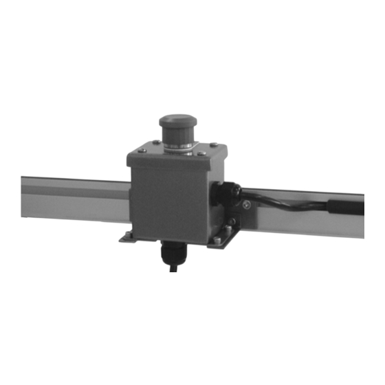
Emergency Stop Kit
. . . . . . . . . . . . . . . . . . . .
. . . . . . . . . .
Setup, Operation
& Maintenance Manual
2
2
3
3
3
. . . . . . . . . . . . . . . . . . . . . . . . . . . . . . . .
. . . . . . . . . . . . . . . . . . . . . . . . . . . . . . .
3
. . . . . . . . . . . . . . . . . . . . . . . . . . . . . . .
4
Table of Contents
. . . . . . . .
. . . . . . . . . .
. . . . . . . . .
851-462 Rev. B
4
. . . . .
4
. . . . .
5
5
5
6
7
8
Advertisement
Table of Contents

Summary of Contents for Dorner 70-40
-
Page 1: Table Of Contents
Setup, Operation & Maintenance Manual 70–40 and 70–41 Emergency Stop Kit Table of Contents Warnings – General Safety ....Horizontal Mounting to 6100 Conveyor . -
Page 2: Warnings - General Safety
Dorner’s Limited Warranty applies. regarding discrepancies. D Inspect packages for shipping damage. Contact carrier Dorner reserves the right to make changes at any time regarding damage. without notice or obligation. 70–40 and 70–41 Emergency Stop Kit Setup, Operation & Maintenance Manual 851-462 Rev. -
Page 3: Specifications
Zip Tie (2x) 4 mm Hex Key Wrench (1x) T-slot Cover Strip (5x) M6 Spring Nut (2x) 6100 Mounting Clip (2x) Figure 4 70–40 and 70–41 Emergency Stop Kit Setup, Operation & Maintenance Manual Dorner Mfg. Corp. 851-462 Rev. B... -
Page 4: Horizontal Mounting To 2100, 2200 & 3100 Conveyor
Install mounting clips (N of Figure 7) on conveyor. Attach Pushbutton Box assembly (G of Figure 9) to mounting plate (B) with screws (E). 70–40 and 70–41 Emergency Stop Kit Setup, Operation & Maintenance Manual 851-462 Rev. B Dorner Mfg. Corp. -
Page 5: Horizontal Mounting To Aluminum Stand Leg
(E). Install two Spring Nuts (N of Figure 11) into Leg Attach Pushbutton Box assembly to Spring Nuts slot. (N) with screws (C). 70–40 and 70–41 Emergency Stop Kit Setup, Operation & Maintenance Manual Dorner Mfg. Corp. 851-462 Rev. B... -
Page 6: Cable Routing
Conveyor The Conveyor T-Slot channel or optional 6 ft (1829mm) or 12.5-ft (3810 mm) Wire Troughs (Dorner #75-85-6 or #75-85-12) can be used to route Figure 14 wire. Figure 15 shows a typical wire routing of an E-Stop... -
Page 7: Service Parts
Power Module (For Illuminated Only) 830–145 Contact Block (for Illuminated only) 830–146 Contact Block (for Both Models) 805–655 Relay 805–053 Power Cord 805–805 Motor Cord Figure 16 70–40 and 70–41 Emergency Stop Kit Setup, Operation & Maintenance Manual Dorner Mfg. Corp. 851-462 Rev. B... -
Page 8: Return Policy
Authorization Number to reference. There will be a 15% restocking charge on all new items returned for credit where Dorner was not at fault. These will not be accepted after 60 days from original invoice date. The restocking charge covers inspection, cleaning, disassembly, and reissuing to inventory.


Need help?
Do you have a question about the 70-40 and is the answer not in the manual?
Questions and answers