Dorner AquaGard 7350 Series Installation, Maintenance, And Parts Manual
Belted conveyors
Hide thumbs
Also See for AquaGard 7350 Series:
- Installation, maintenance, and parts manual (60 pages) ,
- Installation, maintenance & parts manual (20 pages) ,
- Installation, maintenance, and parts manual (36 pages)

Subscribe to Our Youtube Channel
Related Manuals for Dorner AquaGard 7350 Series


Summary of Contents for Dorner AquaGard 7350 Series
- Page 1 7350 Series Version 2 Belted Conveyors Installation, Maintenance and Parts Manual For other service manuals visit our website at: www.dornerconveyors.com/manuals-literature Record Conveyor Serial Number Here 851-879 Rev. C...
-
Page 2: Table Of Contents
B - Idler Spindle Replacement ........34 C - Drive Spindle Replacement........35 Bearing Replacement ............. 36 Drive and Idler Bearing Replacement ......36 Center Drive Bearing Replacement......36 7350 Series Version 2 Belted Conveyors Dorner Mfg. Corp. 851-879 Rev. C... -
Page 3: Introduction
The Dorner Limited Warranty applies. CAUTION Dorner 7350 Series conveyors have patents pending. Some illustrations may show guards Dorner reserves the right to make changes at any time without notice or obligation. removed. DO NOT operate equipment without guards. Dorner has convenient, pre-configured kits of Critical Service Parts for all conveyor products. -
Page 4: Warnings - General Safety
Handle drive shaft keyway with care. It may be sharp and could puncture the skin, causing SEVERE HAZARD! serious injury. • Dorner cannot control the physical installation and application of conveyors. Taking protective measures is the responsibility of the user. • When conveyors are used in conjunction with... -
Page 5: Product Description
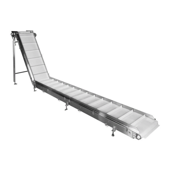
Product Description Refer to (Figure 1) for typical conveyor components. Conveyor Gearmotor Belt (Flat Belt Shown) Support Stands Drive End Idler End Guides Figure 1 Figure 1 7350 Series Version 2 Belted Conveyors 851-879 Rev. C Dorner Mfg. Corp. -
Page 6: Specifications
Tail 1 Auxiliary Shaft Option Auxiliary Shaft Exists Cleat Spacing Cleat Type Profiles Idler Stand Location Drive Stand Location Drive Position Drive Type V-Guide Conveyor Length Conveyor Width Document Language 7350 Series Version 2 Belted Conveyors Dorner Mfg. Corp. 851-879 Rev. C... -
Page 7: Flat Belt Lpz 7350 Series Version 2
Cleat Spacing Cleat Type Profiles Idler Stand Location Drive Stand Location Drive Position V-Guide Direction Angle L3 Section Length L2 Section Length L1 Section Length Conveyor Width Document Language 7350 Series Version 2 Belted Conveyors 851-879 Rev. C Dorner Mfg. Corp. -
Page 8: Conveyor Supports
• Non-accumulating product • Product moving toward gearmotor • Conveyor being mounted horizontally • Conveyor being located in a dry environment • Conveyor equipped with standard belt only 7350 Series Version 2 Belted Conveyors Dorner Mfg. Corp. 851-879 Rev. C... -
Page 9: Installation
Join both conveyor sections and install connecting plates (Figure 4, item 1) with four screws (Figure 4, item 2) on both sides. Tighten to 14-16 ft-lbs (19-22 Nm). 7350 Series Version 2 Belted Conveyors 851-879 Rev. C Dorner Mfg. Corp. -
Page 10: Z-Frame Conveyors
Figure 7 Figure 9 Install belt. Refer to “Belt Installation” on page 12. Install bearing guard and bearing. Tighten all screws to 14-16 ft-lbs (19-22 Nm). Figure 7 7350 Series Version 2 Belted Conveyors Dorner Mfg. Corp. 851-879 Rev. C... -
Page 11: Lower Knuckles
Figure 11 Figure 13 Install belt. Refer to “Belt Installation” on page 12. Figure 11 Install bearing guard and bearing. Tighten all screws to 14-16 ft-lbs (19-22 Nm). 7350 Series Version 2 Belted Conveyors 851-879 Rev. C Dorner Mfg. Corp. -
Page 12: Stand Installation
Position the stands on a flat, level surface. Attach the stands (Figure 15, item 1) to the frame. Tighten screws to 14-16 ft-lbs (19-22 Nm). Figure 15 Figure 17 Figure 15 7350 Series Version 2 Belted Conveyors Dorner Mfg. Corp. 851-879 Rev. C... -
Page 13: Belt Returns
(Figure 20, item 1) to level tail (as needed). Figure 20 Figure 20 Repeat procedure for the opposite end of the conveyor Figure 22 to fully install the belt. 7350 Series Version 2 Belted Conveyors 851-879 Rev. C Dorner Mfg. Corp. - Page 14 Tighten nuts (Figure 27, item 3). Figure 27 Figure 24 Install return clip (Figure 25, item 1) and loosely secure with nut (Figure 25, item 2). Figure 27 Figure 25 Figure 25 7350 Series Version 2 Belted Conveyors Dorner Mfg. Corp. 851-879 Rev. C...
-
Page 15: Cleated Belt And Flat Belt Returns
Install each puck (Figure 32, item 1) onto return bracket (Figure 32, item 2) with stub shaft (Figure 32, item 3) and spacer (Figure 32, item 4). Figure 32 Figure 29 Figure 32 7350 Series Version 2 Belted Conveyors 851-879 Rev. C Dorner Mfg. Corp. -
Page 16: Guide Installation
Figure 38 Assemble the mounting block (Figure 35, item 1) to the conveyor side with the screw (Figure 35, item 2), provided. Figure 35 Figure 38 Figure 35 7350 Series Version 2 Belted Conveyors Dorner Mfg. Corp. 851-879 Rev. C... -
Page 17: Adjustable Guides
Install guide rail (Figure 40, item 1) into rail clamp. Figure 41 Tighten fastener to secure (Figure 40, item 2). Figure 40 Figure 40 NOTE See pages 66 to 69 for detailed view of guide assembly. 7350 Series Version 2 Belted Conveyors 851-879 Rev. C Dorner Mfg. Corp. -
Page 18: Preventive Maintenance And Adjustment
Conveyor Belt Replacement CAUTION WARNING Dorner recommends cleaning all the “food zones” prior to placing conveyor into service. Ensure adequate access is provided for cleaning and servicing equipment so that the required level of hygiene can be SEVERE HAZARD! maintained. - Page 19 Figure 46 Figure 44 Repeat procedure for the opposite end of the conveyor to fully remove the belt. Figure 44 7350 Series Version 2 Belted Conveyors 851-879 Rev. C Dorner Mfg. Corp.
-
Page 20: Center Drive Conveyor Belt Replacement
Tip up tail (Figure 50, item 1). Figure 50 Exposed moving parts can cause severe injury. REMOVE COMPRESSED AIR SUPPLY before removing guards or performing maintenance. Figure 50 7350 Series Version 2 Belted Conveyors Dorner Mfg. Corp. 851-879 Rev. C... - Page 21 Figure 52 Figure 54 Figure 52 Figure 54 Loosen screw (Figure 54, item 2) on each side of the center drive. 7350 Series Version 2 Belted Conveyors 851-879 Rev. C Dorner Mfg. Corp.
- Page 22 15. Slide shaft (Figure 59, item 1) into the tensioner pulley (Figure 59, item 2). Remove the tensioner pulley. Figure 59 Figure 56 Figure 59 7350 Series Version 2 Belted Conveyors Dorner Mfg. Corp. 851-879 Rev. C...
- Page 23 Figure 63 Figure 61 Figure 63 Figure 61 19. Repeat procedure for the opposite end of conveyor. 7350 Series Version 2 Belted Conveyors 851-879 Rev. C Dorner Mfg. Corp.
-
Page 24: Belt Installation
Figure 64 Install belt (Figure 65, item 1) on conveyor. Lift conveyor (Figure 65, item 2) slightly to avoid pinching belt on temporary support stands. Figure 65 Figure 65 7350 Series Version 2 Belted Conveyors Dorner Mfg. Corp. 851-879 Rev. C... -
Page 25: Conveyor Belt Tensioning
10" (254 mm) 15-50 psi (103-345 kPa) 14" (356 mm) 15-60 psi (103-414 kPa) 18" (457 mm) 15-70 psi (103-483 kPa) 24" (610 mm) & wider 15-80 psi (103-552 kPa) 7350 Series Version 2 Belted Conveyors 851-879 Rev. C Dorner Mfg. Corp. -
Page 26: B - With Manual Tensioning
(Figure 70, item 2) is completely behind the spring cover (Figure 70, item 3). There should be approximately a 1/8" gap (Figure 71, item 1) between knob and spring cover. Figure 70 Figure 70 7350 Series Version 2 Belted Conveyors Dorner Mfg. Corp. 851-879 Rev. C... -
Page 27: Conveyor Belt Tracking
(Figure 73, item 1) to 14-16 ft-lbs (19-22 Nm). If the belt is not tracking normally, adjust the cam on the side where the belt is running tight. 7350 Series Version 2 Belted Conveyors 851-879 Rev. C Dorner Mfg. Corp. -
Page 28: Drive Spindle Replacement
Repeat for opposite side headplate (Figure 79, item 3). If necessary, refer to “Bearing Replacement” on page 36 for replacing bearing in each headplate. Figure 76 10. Install parts in reverse order of removal. 7350 Series Version 2 Belted Conveyors Dorner Mfg. Corp. 851-879 Rev. C... -
Page 29: Idler Spindle Replacement
Figure 80 Figure 83 Loosen two set screws (Figure 84, item 1). Figure 80 Remove support bracket (Figure 81, item 1). Figure 84 Figure 81 Figure 84 Figure 81 7350 Series Version 2 Belted Conveyors 851-879 Rev. C Dorner Mfg. Corp. -
Page 30: Nose Bar Idler Spindle Replacement
(Figure 87, item 2) to move idler tail up or down to level with conveyor bed rail. Ensure that nuts are tight after leveling. Figure 87 Figure 89 Figure 87 7350 Series Version 2 Belted Conveyors Dorner Mfg. Corp. 851-879 Rev. C... - Page 31 Figure 94 Figure 91 Remove nose bar puck (Figure 92, item 1). Figure 92 Figure 94 Figure 92 Repeat as needed. Install parts in reverse order of removal. 7350 Series Version 2 Belted Conveyors 851-879 Rev. C Dorner Mfg. Corp.
-
Page 32: Center Drive Spindle Replacement
(Figure 95, item 1) from the center drive. Figure 95 Figure 97 Remove four screws (Figure 98, item 1) and cover (Figure 98, item 1). Figure 98 Figure 95 Figure 98 7350 Series Version 2 Belted Conveyors Dorner Mfg. Corp. 851-879 Rev. C... - Page 33 Figure 104 Remove two screws (Figure 101, item 1) from plate (Figure 101, item 2) on both sides of the center drive. Figure 101 Figure 104 Figure 101 7350 Series Version 2 Belted Conveyors 851-879 Rev. C Dorner Mfg. Corp.
-
Page 34: B - Idler Spindle Replacement
Remove screw (Figure 107, item 1) from each side of the center drive from the idler guard assembly. Figure 107 Figure 107 Loosen screw (Figure 107, item 2) on each side of the center drive. 7350 Series Version 2 Belted Conveyors Dorner Mfg. Corp. 851-879 Rev. C... -
Page 35: C - Drive Spindle Replacement
Complete steps 6 thru 15 of the Center Drive “Belt Removal” on page 20”. Remove gearmotor and gear reducer. See Center Drive Package Manual 851-884 for detailed instructions. Figure 114 7350 Series Version 2 Belted Conveyors 851-879 Rev. C Dorner Mfg. Corp. -
Page 36: Bearing Replacement
Insert bearing (Figure 115, item 1) into housing slot. Locate anti-rotation nub (Figure 115, item 3) to align with slot (Figure 115, item 2) and twist bearing into housing. 7350 Series Version 2 Belted Conveyors Dorner Mfg. Corp. 851-879 Rev. C... -
Page 37: Knuckle Maintenance
Figure 117 Remove bearing guard (Figure 118, item 1) with bearing. Figure 118 Figure 120 Remove lower shaft assembly (Figure 121, item 1). Figure 121 Figure 118 Figure 121 7350 Series Version 2 Belted Conveyors 851-879 Rev. C Dorner Mfg. Corp. - Page 38 The spacers MUST be away from each other. reassembled in the same location. Figure 125 Figure 123 Figure 123 Figure 125 Install lower shaft assembly in reverse order of removal. 7350 Series Version 2 Belted Conveyors Dorner Mfg. Corp. 851-879 Rev. C...
-
Page 39: Upper Knuckle
Remove upper shaft assembly (Figure 130, item 1). Figure 130 Figure 127 Remove bearing (Figure 128, item 1). Figure 128 Figure 130 Figure 128 Install parts in reverse order of removal. 7350 Series Version 2 Belted Conveyors 851-879 Rev. C Dorner Mfg. Corp. - Page 40 The spacers MUST be away from each other. reassembled in the same location. Figure 134 Figure 132 Figure 132 Figure 134 Install upper shaft assembly in reverse order of removal. 7350 Series Version 2 Belted Conveyors Dorner Mfg. Corp. 851-879 Rev. C...
-
Page 41: Belt Return Maintenance
Remove belt return assembly (Figure 136, item 1) from return brackets (Figure 136, item 2). Figure 138 Figure 136 Repeat steps 3 through 5 as needed. Figure 136 7350 Series Version 2 Belted Conveyors 851-879 Rev. C Dorner Mfg. Corp. -
Page 42: Cleated Belt And Flat Belt Returns Under 508 Mm Wide
Figure 142 Figure 140 Figure 142 Replace worn or damaged parts. Figure 140 Install parts in reverse order of removal. Install belt return assembly in reverse order of removal. 7350 Series Version 2 Belted Conveyors Dorner Mfg. Corp. 851-879 Rev. C... -
Page 43: Notes
Notes 7350 Series Version 2 Belted Conveyors 851-879 Rev. C Dorner Mfg. Corp. -
Page 44: Service Parts
Service Parts NOTE For replacement parts other than those shown in this section, contact an authorized Dorner distributor or Dorner directly. Recommended Critical Service Parts and Kits are identified by the Key Service Parts symbol . Dorner recommends keeping these parts on hand. - Page 45 WW = Conveyor width reference in inches 06 - 36 in 02 increments See Specifications chart on page 8 for conveyor belt widths. Service parts can be obtained through your distributor or directly from Dorner Mfg. Corp. (800) 397-8664 or customerservice@dorner.com 7350 Series Version 2 Belted Conveyors 851-879 Rev. C...
-
Page 46: Tip-Up Idler Tail
Service Parts Tip-Up Idler Tail 25 Idler Tail Kit 7350 Series Version 2 Belted Conveyors Dorner Mfg. Corp. 851-879 Rev. C... - Page 47 WW = Conveyor width reference in inches 06 - 36 in 02 increments See Specifications chart on page 8 for conveyor belt widths. Service parts can be obtained through your distributor or directly from Dorner Mfg. Corp. (800) 397-8664 or customerservice@dorner.com 7350 Series Version 2 Belted Conveyors 851-879 Rev. C...
-
Page 48: Fixed Idler Tail For Center Drive Conveyors
Service Parts Fixed Idler Tail for Center Drive Conveyors 15 Idler Tail Kit Auxiliary Shaft Shown 7350 Series Version 2 Belted Conveyors Dorner Mfg. Corp. 851-879 Rev. C... - Page 49 WW = Conveyor width reference in inches 06 - 36 in 02 increments See Specifications chart on page 8 for conveyor belt widths. Service parts can be obtained through your distributor or directly from Dorner Mfg. Corp. (800) 397-8664 or customerservice@dorner.com 7350 Series Version 2 Belted Conveyors 851-879 Rev. C...
-
Page 50: Tip-Up Nose Bar Idler Tail
Service Parts Tip-Up Nose Bar Idler Tail 27 Nose Bar Idler Tail Kit 7350 Series Version 2 Belted Conveyors Dorner Mfg. Corp. 851-879 Rev. C... - Page 51 WW = Conveyor width reference in inches 06 - 36 in 02 increments See Specifications chart on page 8 for conveyor belt widths. Service parts can be obtained through your distributor or directly from Dorner Mfg. Corp. (800) 397-8664 or customerservice@dorner.com 7350 Series Version 2 Belted Conveyors 851-879 Rev. C...
-
Page 52: Fixed Nose Bar Idler Tail For Center Drive Conveyors
Service Parts Fixed Nose Bar Idler Tail for Center Drive Conveyors 12 Nose Bar Idler Tail Kit 7350 Series Version 2 Belted Conveyors Dorner Mfg. Corp. 851-879 Rev. C... - Page 53 WW = Conveyor width reference in inches 06 - 36 in 02 increments See Specifications chart on page 8 for conveyor belt widths. Service parts can be obtained through your distributor or directly from Dorner Mfg. Corp. (800) 397-8664 or customerservice@dorner.com 7350 Series Version 2 Belted Conveyors 851-879 Rev. C...
-
Page 54: Center Drive Module
Service Parts Center Drive Module 26 Center Drive Spindle Kit 7350 Series Version 2 Belted Conveyors Dorner Mfg. Corp. 851-879 Rev. C... - Page 55 WW = Conveyor width reference in inches 06 - 36 in 02 increments See Specifications chart on page 8 for conveyor belt widths. Service parts can be obtained through your distributor or directly from Dorner Mfg. Corp. (800) 397-8664 or customerservice@dorner.com 7350 Series Version 2 Belted Conveyors 851-879 Rev. C...
-
Page 56: Frame
Service Parts Frame 7350 Series Version 2 Belted Conveyors Dorner Mfg. Corp. 851-879 Rev. C... - Page 57 LLLLL = Part length in inches with 2 decimal places. Example: Part Length = 95.25" LLLLL = 09525 Service parts can be obtained through your distributor or directly from Dorner Mfg. Corp. (800) 397-8664 or customerservice@dorner.com 7350 Series Version 2 Belted Conveyors 851-879 Rev.
-
Page 58: Upper Knuckle
Service Parts Upper Knuckle 14 Knuckle Kit 7350 Series Version 2 Belted Conveyors Dorner Mfg. Corp. 851-879 Rev. C... - Page 59 LLLLL = Part length in inches with 2 decimal places. Example: Part Length = 95.25" LLLLL = 09525 Service parts can be obtained through your distributor or directly from Dorner Mfg. Corp. (800) 397-8664 or customerservice@dorner.com 7350 Series Version 2 Belted Conveyors 851-879 Rev.
-
Page 60: Lower Knuckle
Service Parts Lower Knuckle 15 Knuckle Kit 7350 Series Version 2 Belted Conveyors Dorner Mfg. Corp. 851-879 Rev. C... - Page 61 LLLLL = Part length in inches with 2 decimal places. Example: Part Length = 95.25" LLLLL = 09525 Service parts can be obtained through your distributor or directly from Dorner Mfg. Corp. (800) 397-8664 or customerservice@dorner.com 7350 Series Version 2 Belted Conveyors 851-879 Rev.
-
Page 62: Connecting Assembly
Connecting Plate 960810MSS Hex Head Cap Screw, M8-1.25 x 10 mm Service parts can be obtained through your distributor or directly from Dorner Mfg. Corp. (800) 397-8664 or customerservice@dorner.com 7350 Series Version 2 Belted Conveyors Dorner Mfg. Corp. 851-879 Rev. C... -
Page 63: 25 Mm High Sides
Multiple Guide Sections Only) Example: Part Length = 95.25" LLLLL = 09525 990801MSS Hex Nut Service parts can be obtained through your distributor or directly from Dorner Mfg. Corp. (800) 397-8664 or 518400-01-LLLLL-LH Guiding, Left Hand (for Multiple customerservice@dorner.com Guide Sections Only) -
Page 64: Mm High Sides
Multiple Guide Sections Only) Example: Part Length = 95.25" LLLLL = 09525 990801MSS Hex Nut Service parts can be obtained through your distributor or directly from Dorner Mfg. Corp. (800) 397-8664 or 518400-03-LLLLL-LH Guiding, Left Hand (for Multiple customerservice@dorner.com Guide Sections Only) -
Page 65: 152 Mm High Sides
Multiple Guide Sections Only) Example: Part Length = 95.25" LLLLL = 09525 990801MSS Hex Nut Service parts can be obtained through your distributor or directly from Dorner Mfg. Corp. (800) 397-8664 or 518400-06-LLLLL-LH Guiding, Left Hand (for Multiple customerservice@dorner.com Guide Sections Only) -
Page 66: Fully Adjustable Round Guides
807-015 Rail Clamp Service parts can be obtained through your distributor or directly 807-1387 Cross Block Clamp from Dorner Mfg. Corp. (800) 397-8664 or 960812MSS Hex Head Cap Screw, customerservice@dorner.com M8-1.25 x 12 mm 7350 Series Version 2 Belted Conveyors Dorner Mfg. -
Page 67: Tool-Less Fully Adjustable Round Guides
807-015 Rail Clamp Service parts can be obtained through your distributor or directly 807-1470 Cross Block Clamp from Dorner Mfg. Corp. (800) 397-8664 or 960812MSS Hex Head Cap Screw, customerservice@dorner.com M8-1.25 x 12 mm 7350 Series Version 2 Belted Conveyors 851-879 Rev. -
Page 68: Fully Adjustable Flat Guides
807-015 Rail Clamp Service parts can be obtained through your distributor or directly 807-1387 Cross Block Clamp from Dorner Mfg. Corp. (800) 397-8664 or 960812MSS Hex Head Cap Screw, customerservice@dorner.com M8-1.25 x 12 mm 7350 Series Version 2 Belted Conveyors Dorner Mfg. -
Page 69: Tool-Less Fully Adjustable Flat Guides
807-015 Rail Clamp Service parts can be obtained through your distributor or directly 807-1470 Cross Block Clamp from Dorner Mfg. Corp. (800) 397-8664 or 960812MSS Hex Head Cap Screw, customerservice@dorner.com M8-1.25 x 12 mm 7350 Series Version 2 Belted Conveyors 851-879 Rev. -
Page 70: 25 Mm Cleated High Sides
Example: Part Length = 95.25" LLLLL = 09525 Guide Sections Only) Service parts can be obtained through your distributor or directly 518396-01-LLLLL-RH Guiding, Right Hand (for Multiple from Dorner Mfg. Corp. (800) 397-8664 or Guide Sections Only) customerservice@dorner.com 7350 Series Version 2 Belted Conveyors Dorner Mfg. Corp. -
Page 71: Mm Cleated High Sides
Example: Part Length = 95.25" LLLLL = 09525 Guide Sections Only) Service parts can be obtained through your distributor or directly 518396-03-LLLLL-RH Guiding, Right Hand (for Multiple from Dorner Mfg. Corp. (800) 397-8664 or Guide Sections Only) customerservice@dorner.com 7350 Series Version 2 Belted Conveyors 851-879 Rev. C... -
Page 72: 152 Mm Cleated High Sides
Example: Part Length = 95.25" LLLLL = 09525 Guide Sections Only) Service parts can be obtained through your distributor or directly 518396-06-LLLLL-RH Guiding, Right Hand (for Multiple from Dorner Mfg. Corp. (800) 397-8664 or Guide Sections Only) customerservice@dorner.com 7350 Series Version 2 Belted Conveyors Dorner Mfg. Corp. -
Page 73: Flat Belt Returns 508 Mm Wide And Wider
LLLLL = Part length in inches with 2 decimal places. Example: Part Length = 95.25" LLLLL = 09525 Service parts can be obtained through your distributor or directly from Dorner Mfg. Corp. (800) 397-8664 or customerservice@dorner.com 7350 Series Version 2 Belted Conveyors 851-879 Rev. -
Page 74: Cleated Belt And Flat Belt Returns Under 508 Mm Wide
Carriage Bolt, M8 x 16 mm 990801MSS Hex Nut 550369 Puck Kit (Includes item 2) Service parts can be obtained through your distributor or directly from Dorner Mfg. Corp. (800) 397-8664 or customerservice@dorner.com 7350 Series Version 2 Belted Conveyors Dorner Mfg. Corp. 851-879 Rev. C... -
Page 75: Roller Transfer
M6-1.00 x 16 mm WW = Conveyor width reference in inches 08 - 36 in 02 increments Service parts can be obtained through your distributor or directly from Dorner Mfg. Corp. (800) 397-8664 or customerservice@dorner.com 7350 Series Version 2 Belted Conveyors 851-879 Rev. -
Page 76: Configuring Conveyor Belt Part Number
“VG” for 06, 08, 57, 59, and 64 below. *Add “V” for v-guided belts. v-guided belt types. 73C-WWW LLLLL B SSSS V* 73E-WWW LLLLL / BB V* 73C- 73E- (Fill In) (Fill In) 7350 Series Version 2 Belted Conveyors Dorner Mfg. Corp. 851-879 Rev. C... -
Page 77: Notes
Notes 7350 Series Version 2 Belted Conveyors 851-879 Rev. C Dorner Mfg. Corp. -
Page 78: Return Policy
Return Policy Returns must have prior written factory authorization or they will not be accepted. Items that are returned to Dorner without authorization will not be credited nor returned to the original sender. When calling for authorization, please have the following information ready for the Dorner factory representative or your local distributor: Name and address of customer.
Need help?
Do you have a question about the AquaGard 7350 Series and is the answer not in the manual?
Questions and answers