
Related Manuals for FISCHER FERITSCOPE DMP30


Summary of Contents for FISCHER FERITSCOPE DMP30
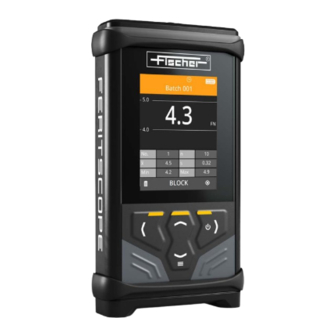
- Page 1 Operator’s Manual Gauge for measurement of the ferrite content in autenitic and duplex steel FERITSCOPE® DMP30...
- Page 2 Industriestraße 21 www.helmut-fischer.com D-71069 Sindelfingen mail@helmut-fischer.com On our home page www.helmut-fischer.com you will find the addresses of our sole agencies and subsidiary companies around the globe. Quality Assurance System of the Helmut Fischer GmbH Institut für Elektronik und Messtechnik DIN EN ISO/IEC 17025 Calibration lab accredited for certified mass per unit...
-
Page 3: Table Of Contents
..........Safety Warnings and icons used . - Page 4 ......... . . Measure Notes on measuring .
- Page 5 ........Batch management 13.1 Assigning/changing batch names ....... . 84 13.2 Copying a batch .
- Page 6 FERITSCOPE® DMP30...
-
Page 7: Safety
Safety ► Refer to the safety information before starting-up this gauge in order to avoid damage to property or personal injury. ► Keep this manual in a safe place to be able to refer to any necessary descrip- tions at a later date. Warnings and icons used ATTENTION Indicates a danger that can lead to damage or destruction of the product. -
Page 8: Intended Use
Intended use The gauge is intended solely for the determination of the -ferrite content of auste- nitic and DUPLEX steel. Factors that influence the measurement accuracy, such as the geometry of the measured object, the thickness of a possible cladding layer or the shape of the permeable structure, must be taken into account individually by the user. - Page 9 via travel charger or PC is possible, but not recommended. The guaranteed confor- mity applies exclusively to battery operation! ATTENTION – Damage due to high temperature When exposed to sunshine, the areas behind glass windows (e.g. in a car) can easily reach temperatures in excess of +50 °C (+122 °F).
-
Page 10: Maintenance And Repairs
► Do not continue to use the battery if you notice any changes such as discoloration, deformation or damage to the outer casing. ► Replace the battery if it is not charged after the usual charging time. The usual charging time can be found in the technical data. -
Page 11: Limitation Of Liability
Limitation of liability The gauge manufacturer accepts no liability and responsibility for any kind of dam- age resulting from the use of the corrective diagrams and tables provided in the chapter "Parameters that influence the Delta-ferrite content measurement". The user uses the formular, corrective diagrams and tables at their own responsibility. The manufacturer accepts no liability for damage of any kind caused by read-off er- rors and unsafe estimates. -
Page 12: Gauge
Lanyard Gauge case Fischer-Bluetooth stick Gauge Battery compartment lid, Bluetooth in- terface Light strip for displaying the mea- sured reading acquisition, specifica- tion limit violation, battery charge status Display Operation keys, : on/off (press for approx. 2 s) -
Page 13: Overview Of Signals
Overview of signals If all signal functions in the gauge are activated, the gauge reports the following states: Beeps Short beep = measured reading acquisition complete, second beep in addition if the specification limit is violated Long beep = block closure ... - Page 14 Calls up the Delete function Opens another menu page Scrolls, displays the next page Confirm the message/information Starts the function (e.g. Delete function) Cancels the setting process and exits the function or returns to the previous page without saving any changes CLOSE Sets a block closure when the block statistics are exited;...
-
Page 15: Measurement View
Measurement view Batch name Batch 004 Specification limits 71.3 75.0 Reading currently being measured Statistical values 55.0 Key assignment line (example: delete function, block statistics, calibration function) 65.04 4.77 Status displays; icons indicate active 61.8 71.3 autom. gauge shutdown (clock), bat- BLOCK tery charge status or the active con- Example of the Measurement... - Page 16 Red icon: the gauge cannot communicate with the inserted Bluetooth stick. In- sert the Fischer-Bluetooth stick. Gray icon: the socket in the gauge for the Fischer-Bluetooth stick is empty, but the Bluetooth function is switched on. Free Running measuring mode active...
- Page 17 On/Off switch, – parameter/function is deactivated Parameter selection – parameter/function is activated Parameter selection – parameter/function is deactivated Number of the current block Number of measured readings Number of measured readings in the current/selected block Number of all measured readings in the current batch Arithmetic mean of the current block with n measured readings Standard deviation for the arithmetic mean ;...
-
Page 18: Menus - Function Overview
Menus – function overview Menu Statistics View of the statistics for the open batch Batch Modify menu Settings and entries for the open batch > Batch Modify MEASURE Opens the Measurement view, starts the measurement with the probe posi- tioned on the specimen surface Batch Modify >... - Page 19 Batch Modify > More Settings > Calibration Assign Assigns a different calibration Menu Batches > Batches New, starts a routine for creating a new batch in the gauge. Batches > List containing the batches stored in the gauge; ...
- Page 20 Gauge Settings menu > Gauge Settings Language Selects the display language Gauge Settings > Display Settings Activates/deactivates display flip function and display brightness Gauge Settings > Signal Settings Audible signal on/off Activates/deactivates the visual signals and sets the luminosity Vibration on/off Gauge Settings >...
-
Page 21: Statistical Characteristic Variables
Statistical characteristic variables – Mean Value Arithmetic mean value ( ) of all measured readings. The arithmetic mean value is the summation of all measured readings xi of a batch or block, divided by the num- ber of measured readings (n). n –... -
Page 22: Technical Data
Technical Data Description The FERITSCOPE® FMP30 determines the delta-ferrite content of austenitic and Du- plex steels using the magnetic inductive test method. All magnetizable structure sections are captured i. e., in addition to delta-ferrite also strain-induced martensite, for example, or other ferritic phases. A specific advantage of the magnetic induction method for measuring the ferrite content is that a sigma phase, i. - Page 23 Applications Determination of delta-ferrite content of austenitic and duplex steel Determination of deformation martensite in austenitic materials Finding weld seams in polished surfaces Capturing a ferrite content profile along the weld seam Metrological Features Measurement acquisition Default: After each placement of the probe onto the surface, a measured read- ...
- Page 24 Limit Monitoring Can be disabled; limit values can be set Offset value/ correction value Can be set, is deducted automatically from the measured reading. Resolution of the displayed values Low (up to 1 decimal place) Medium (up to 2 decimal places) ...
- Page 25 Calibration method Adjustment of the measuring system (gauge and connected probe) to a zero point (base) and adjustment to up to three ferrite content values by using calibration stan- dards. On recalibration, individual calibration steps can be skipped. Store calibrations The storage location for a calibration depends of the connected probe.
- Page 26 Dynamic: automatic acceptance of the air value always when the probe is lifted from the surface, default mode Static: no automatic acceptance of the air value always when the probe is lifted from the surface. In this case, the air reference value must be measured man- ually at regular intervals.
-
Page 27: Data Transmission
Data transmission via USB via Bluetooth® only with Fischer-Bluetooth® stick Data export via Tactile Suite to Excel® (online, offline) Data retrival by Tactile Suite: batches, single readings, batch statistics and block statistics Test method on basis of DIN EN ISO 2178 / ASTM D7091 magnetic induction test method... -
Page 28: Protection Class
Connections 2 USB female jacks, type C USB 3.1, 900 mA/5 V=, at gauge bottom: for connecting digital Fischer probe for fast charging the Li-Ion rechargeable battery in the gauge USB 3.1, 500 mA/5 V=, at gauge top: for charging the Li-Ion rechargeable... -
Page 29: Order Information
38 mm 1.10 " 1,50 " Scope of supply Gauge, Li-Ion rechargeable battery, USB cable type C to type A (1,5 m/59.06 "), safety information and quick guide, lanyard, gauge case, Fischer-Bluetooth® stick Order Information Gauge Order number: 1007334 ... - Page 30 Gauge support stand: 1008201 USB cable: 1008215 type C to A, 1 m (39.4 ") Fischer-Bluetooth® stick: 1008864 Bluetooth v 4.0. LE, transmit power up to -27 dBm Li-Ion rechargeable battery, model RRC1130: 1008303 Charger for Li-Ion rechargeable battery, model RRC1130: 1008304 ...
-
Page 31: Guide
Guide All relevant settings for measuring and the mea- Batch 004 sured readings themselves are saved in the gauge in 73.3 a file. Such a file is called a batch. In order to mea- 75.0 sure, you must assign to the batch a calibration (ref- erence) that is saved in the connected probe. -
Page 32: Rechargeable Battery
Rechargeable battery This chapter contains important instructions on handling, changing and charging the battery. CAUTION – when handling the battery Improper handling of the battery can cause the battery to overheat, leak or burst. ► Use only batteries specified by the manufacturer to operate this gauge: Type RRC 1130 (3.8 V, 14.47 Wh, scope of supply) ►... - Page 33 To change the battery Make sure the battery is the right way round! What you can do next Charge the battery using the charger (available from Fischer as an accessory) for battery type RRC 1130 Continue the measurement ...
-
Page 34: Charging The Battery
Charging the battery ATTENTION –Make sure the charging power is correct Whether you use a standard travel charger or an external charger, always make that the battery is charged to the correct power: Nominal voltage: 3.8 V= Nominal capacity: 3880 mA, 14.7 Wh max. - Page 35 USB-C plug of charging cable Alternative 2 – charge the battery using an external charger for model RRC1130 (available from Fischer as an accessory). a Switch off the gauge, b Remove the battery from the gauge, c Refer to the safety Information, d Place the battery in the external charger.
-
Page 36: Connecting/Replacing Probe
Connecting/replacing probe Every probe has its own identifier, consisting of a probe code (e.g. D-FN) and the se- rial number. Each time a batch (measuring application, application) is created, the probe identifier is automatically saved as well. This ensures that for the open batch, a measurement can be performed only using the probe that has the same identifier as the one saved in the open batch. - Page 37 Probe Analog probes (F…) with 12-pin connecting plug via DMP-F probe adapter (1007336, available from Fischer as an accessory) To attach the DMP-F probe adapter to the gauge. DMP-F probe adapter To connect the probe to the DMP-F probe adapter.
-
Page 38: Replacing The Probe - Connecting A Different Probe
Replacing the probe – connecting a different probe You can replace a defective probe with a new probe of the same type or connect a different probe type to the one previously used. ATTENTION – Data loss If a new probe is assigned to a batch, all previous measured readings of the batch will be lost since the measured readings previously stored in the batch were measured using a different probe and a different calibration. - Page 39 3. Open the most recently opened batch: 4. The Reassign probe? menu page appears. The menu page displays the probe identifiers of the two probes: the old one previously assigned to the batch, and the connected new probe. 5. Assign the connected probe to the batch: OK. A message tells you that a calibration still needs to be assigned to the open batch.
-
Page 40: Settings For Measurement
Settings for measurement In order to measure, you need to create and open a batch (measuring file). Settings, such as those for the measurement procedure are saved in the batch, e.g. specifica- tion limit monitoring and grouping of measured readings in measurement blocks during the measurement and in measuring mode. -
Page 41: Opening A Batch
4. Make the desired batch settings for the measurement 35, assign a batch name, This completes the creation process for a new batch. 5. Call up the Measurement view for the new batch: MEASURE > OK. Creating a new batch by copying You use the Copy function to create a batch by copying a selected batch. -
Page 42: Activating/Deactivating Automatic Block Formation
To activate specification limit monitoring and set the specification limits 1. Select the specification limits to be monitored: > Batch Modify > OK > Limits > OK > select desired specification limit parameter > OK. Parameter is activated: The selected specification limit(s) with the currently set values appear in the specification limit menu. -
Page 43: Activating/Deactivating Offset Function
To activate automatic block formation and set the desired block size > Batch Modify > OK > Block Size > OK > Generate autom. > OK. Parameter is activated: 2. Set the block size: Block Size > OK > set desired value > OK. 3. -
Page 44: Selecting Measuring Mode
Selecting measuring mode You can specify how the measured readings are to be acquired and displayed. Single Readings (default mode) Measured reading acquisition after the probe is placed on the surface. The measured readings are automatically saved in the batch (measurement file), provided the Save Readings function is activated. - Page 45 parameter (time interval) set in Scan measuring mode, a measured reading is acquired every x seconds as the surface is being scanned. After n measured readings, automatic measured reading acquisition stops. The measurement cy- cle is repeated when the probe is applied again. The setting for the number of measured readings per block in the Block Size is used as the number of mea- sured readings.
-
Page 46: Save Measured Readings On/Off
Save measured readings on/off You can specify whether the measured readings are automatically saved in the open batch. Function activated (default mode) The measured reading is automatically saved in the open batch with every measured reading acquisition. Function deactivated The measured readings are automatically saved in the open batch only temporarily. When a different batch is called or the gauge is switched off, the measured readings are lost. -
Page 47: Assigning A Different Calibration To The Opened Batch
You can choose between automatic (dynamic) and manual (static) acquisition of the air reference value: Dynamic (default mode) Dynamic, automatic acquisition of the air value each time the probe is lifted off the surface. Static Static, no automatic acquisition of the air value each time the probe is lifted off the surface. -
Page 48: Measure
Measure Measurement influencing factors do not significantly affect the FERITSCOPE® DMP30. Ferrite content measurements can be carried out regardless of the sub- strate material properties starting at a plating thickness of 3 mm (0.12 "). Due to the used magnetic induction measuring method, which captures all ferromagnetic com- ponents in the same manner, the measurements are always stated in -ferrite. -
Page 49: Handling The Probe
If all signal functions in the gauge are activated, the gauge reports the following states: Beeps Short beep = measured reading acquisition complete, second beep in addi- tion if the specification limit is violated Long beep = block closure Light signals Specification limit monitoring not active: Green = measured reading acquisition successful... -
Page 50: Parameters That Influence The Delta-Ferrite Content Measurement
Parameters that influence the Delta-ferrite content measurement The following factors influence the readings of a -ferrite content measurement: Specimen curvature The influence takes effect from following curvature diameters: - diameters less than 50 mm (1.97 ") for convex curvatures, - diameters less than 80 mm (3.15 ") for concave curvatures. - Page 51 Correction curves for measurement values with measurement unit FN Correction values for values with measurement unit FN measured on specimens with different convex curvature diameters FERITSCOPE® DMP30 Measure...
- Page 52 Correction curves for measurements values with measurement unit Fe% Correction values for values with measurement unit Fe % measured on specimens with different convex curvature diameters Measure FERITSCOPE® DMP30...
-
Page 53: Before You Start
Before you start The measuring area and the probe tip on the probe are clean, free of oil, dust, etc. The probe is connected to the gauge. The gauge is acclimatized and the battery are sufficiently charged for the up- ... -
Page 54: Measuring In Single Reading Measuring Mode - Procedure
Measuring in single reading measuring mode - procedure Measuring on flat specimens - single-tip probe The display screens should be considered only as examples, the gauge default modes are required here for the measured reading acquisition, probe D-F-Fe is shown as a typical example of our axial probes Position the probe Measured reading ac- Lift off the probe... -
Page 55: Measuring In Free-Running Measuring Mode - Procedure
Measuring in free-running measuring mode - procedure No measured readings are saved! Measuring on flat specimens The display screens should be considered only as examples, the gauge default modes are required here for the measured reading acquisition, probe D-F-Fe is shown as a typical example of any probe Position the probe Display measured Lift off the probe... -
Page 56: Measuring In Scan Measuring Mode - Procedure
Measuring in scan measuring mode - procedure Measuring on flat specimens The display screens should be considered only as examples, the gauge default modes are required here for the measured reading acquisition, probe D-FN is shown as a typical example of any probe Position the probe Measured reading ac- Lift off the probe... -
Page 57: Measuring With Manual Recording Of The Air Reference Value
Measuring with manual recording of the air reference value If the minimum lift off distance of 4 x the probe measurement range cannot be main- tained when measuring in cavities and pipes, you can also record the air reference value manually at regular intervals. Before you start Air value recording is set to Static, ... -
Page 58: Calibration
The calibration standards used at Fischer are traceable to internationally recognized secondary standards of the National Institute of Standards and Technology (NIST) for ferrite number (FN). -
Page 59: Overview Of Calibration Methods
In such a case, the probe must be sent to your authorized distributor or directly to Fischer for repair. Overview of calibration methods Zero (zero point, calibration step Zero) This is the simplest type of calibration and is used to calibrate the measuring system to a reference point, which is called zero here (zero point). -
Page 60: Please Observe The Following Information On Calibration/Recalibration
Please observe the following information on calibration/ recalibration The information for precision (remaining deviations from precision to mea- sured reading) and repeatability (repeated standard deviation) applies for the ambient and reference piece temperatures at the time of the calibration. The values for precision and repeatability may be higher than the values indicated in the data sheet if the temperatures during the measurement deviate from the ambient and reference piece temperatures during the calibration. -
Page 61: Recalibration
Recalibration A recalibration is in effect the repeat of an existing calibration. The calibration data are overwritten when a calibration routine is run again. During the recalibration, you can skip individual calibration steps (Zero or Std. 1/2/3). Before you start Refer to the notes on calibration, ... -
Page 62: Required Material
9.4.1 Calibration step Zero – Procedure Measure on the calibration standard Base. Required material Base: calibration standard with very high ferrite content (ca. 100 FN) from the calibration set. To perform the calibration step Zero 1. Perform 5 to 10 measurements on the calibration standard Base. Position the gauge Measured reading Lift off the probe... - Page 63 Display description – Zero calibration step Name of calibration (example) Calibration 003 Schematic illustration of the current cali- bration step Current calibration step Progress display of the calibration steps (example: calibration step 1 current = cal- ibration step Zero) Zero Current measured reading (example) Mean value of the measured readings re- 105 n...
- Page 64 9.4.2 Calibration step Std – procedure Measure on the calibration standard. Required material Calibration standard(s) with the desired ferrite contents from the calibration set To perform the calibration step Std 1. Perform 5 to 10 measurements on the calibration standard (Std. 1). Position the gauge Lift off the probe Measured reading...
- Page 65 Display description – Std calibration step Name of calibration (example) Calibration 003 Schematic illustration of the current cali- bration step Current calibration step Progress display of the calibration steps (example: calibration step 2 current = cal- ibration step Std 1) Std 1 Current measured reading (example) 0.65...
-
Page 66: Calling Up Information About The Calibration
Calling up information about the calibration You can call up information for a selected calibration. Before you start The probe containing the calibration whose information you want to view is connected to the gauge. In the gauge is the batch open to which the calibration is assigned, whose in- ... -
Page 67: Activating/Deactivating Semi-Automatic Calibration Routine
Activating/deactivating semi-automatic calibration routine The Shortened course function activates a semi-automatic calibration routine for the selected calibration. If the Shortened course function is activated, the calibration rou- tine switches automatically to the next calibration step after every 3 measurements. The next calibration step is signaled only through the display of the required stan- dard value. -
Page 68: Calibration - Reset
Calibration - reset You can reset a calibration and delete all the correction values (ferrite content) of the selected calibration. The function deletes all parameters measured in the Std cali- bration steps. The entered standard nominal values and the measurements of the Zero calibration step are retained. -
Page 69: Creating New Calibration
Creating new calibration In the following cases, you have to record the influencing variables with a new cali- bration in order to compensate for them when measuring. You have determined during test measurements that none of the listed calibra- tions is suitable for the specimen at hand. -
Page 70: Calibration - Assigning/Changing Names
Calibration - assigning/changing names Assign a unique name to the calibration (calibration method, material designation, batch no., …), example: Z+1F EN AW 6082 or Z EN AW 6082. Keep in mind that many calibrations can be stored in the probe/DMP-F probe adapter. -
Page 71: Checking The Precision Of A Calibration
6. Did you deactivate the lock function in step 2.? Yes: Reactivate the lock function: Function is activated: No: Continue with step 7. 7. Exit the calibration menu: , the name has now been changed. 9.10 Checking the precision of a calibration The Check Calibration function checks during a control measurement whether the mean value of the control measurement matches the nominal value of the used cal- ibration standard within the measurement uncertainty (in accordance with ISO/IEC... - Page 72 Before you start The test parameters for the selected calibration are defined. Defining the test settings, The probe is connected to the gauge containing the calibration you want to check. In the gauge is the batch open to which the calibration is assigned, you want to ...
- Page 73 : Arithmetic mean value, determined from the measurements taken; red values are outside the tolerance limits s: Standard deviation, determined from the measurements taken; red values are outside the tolerance limits n: Number of measurements taken 5. Start the check: OK 6.
-
Page 74: Defining The Test Criteria For The Calibration Check
9.11 Defining the test criteria for the calibration check You can perform a control measurement to check the precision of a selected calibra- tion. The check is based on the measurement uncertainty (tolerance) specified for the calibration standard used during the control measurement. To be able to check a calibration, you have to enter for this calibration the measurement uncertainty or tolerance for the calibration standard you want to use for the check (control mea- surement). -
Page 75: Lock Calibration
Parameter selection: No: Check function deactivated Abs. Tol., example: ± 0.1 FN Rel. Tol., percentage value, example: ± 1.25 % Uncertainty, example: expanded measurement uncertainty for an expansion factor k=2: ± 0.5 FN 5. Set the nominal value and the tolerance/measurement uncertainty for the cali- bration standard you intend to use for the check (control measurement) later: Reference Value >... -
Page 76: Calibration - Deactivating Lock
To lock a calibration 1. Select the calibration you want to lock: > Calibrations > OK > select name of calibration > OK. 2. Activate the lock function: Lock Calibration > OK. Function is activated: 3. Exit the menu: , the locking process has finished. To access the menu and the calibration routine of the locked calibration, you now need to enter the lock code. -
Page 77: Deleting A Calibration
9.14 Deleting a calibration You can delete individual calibrations from the memory of the probe/DMP-F probe adapter. Before you start The probe is connected to the gauge containing the memory from which you want to delete a calibration. In the gauge is the batch open to which a calibration is assigned for the same ... -
Page 78: Deleting All Calibrations
9.15 Deleting all calibrations You can delete all your calibrations from the memory of the connected probe. This function deletes all the calibration files and all their data! DMP-F probe adapter: You can use this function to delete all calibrations from the DMP-F probe adapter that were created using the connected probe. -
Page 79: Evaluation
Evaluation The gauge provides you with the mathematical calculations, complex and extensive at times, needed for statistical evaluation of the measured readings from the opened batch and the measurement blocks when automatic block formation is switched on. The evaluation refreshes continuously in the background during the measurement. The statistical characteristic variables of the open batch are displayed in the Statis- tics menu. -
Page 80: Block Statistics
10.2 Block statistics Display statistical characteristic variables for each measured reading block: > Statistics > OK > Block Statistics BLOCK. 63.51 : Scroll through the individual block statistics 2.94 (block no. 1 to x) V[%] 60.9 67.7 Description of the characteristic variables, see <LSL >USL page 15... -
Page 81: Data Transfer
CSV format. You can download the Tactile Suite program free of charge from the Fischer down- load page. Information on how to use the Tactile Suite software program can be found in the corresponding Operator's Manual ( Tactile Suite). -
Page 82: Data Transfer Via Usb
11.1 Data transfer via USB Before you start The Tactile Suite software program is installed on the PC and opened. The gauge is switched off. The USB cable from the scope of supply is ready. For the data transfer, use the USB cable from the scope of supply or any other commercially available USB cable with a C/A-type plug;... -
Page 83: Data Transfer Via Bluetooth
11.2 Data transfer via Bluetooth To transfer data using Bluetooth®, you need the special Fischer-Bluetooth stick, in- cluded in the scope of supply. Before you start The Tactile Suite software program is installed on the PC. The Fischer-Bluetooth stick from the scope of supply is ready. - Page 84 , the settings in the gauge are now made. 5. PC: Establish the Bluetooth connection to your PC. Add the gauge (Helmut Fischer GmbH BT Device) as a new gauge or refresh the connection. Gauge: A blue Bluetooth icon appears in the uppermost header to indicate that a Bluetooth connection has been established.
-
Page 85: Batch Settings
Batch settings For the open batch, you can make settings that do not directly affect the measure- ment, such as changing the Measurement view, the max. number of decimal places for the displayed values or calling up the batch information. 12.1 Calling up information about the open batch You can call up information about the open batch. - Page 86 Measurement View Type of Measurement view set for this batch (Simple, Statistics). Meas. unit FN (example) Block Size Number of measured readings collected in a block. Offset Information about the offset: off or set offset value. Measure Mode Information about the set measuring mode: Single Readings, Free Running or Scan with the set scan parameters Values rounding Information about the resolution of the displayed values: number of decimal places...
-
Page 87: Selecting The Measurement View For The Batch
12.2 Selecting the Measurement view for the batch You can display various items of additional information for the open batch. You can choose between two Measurement views. The display screens below should be considered only as examples; batch 004 has set specifica- tion limits. -
Page 88: Selecting Characteristic Variables For The Statistical Displays
2. Have you selected the Statistics Measurement view? Yes: Select the desired characteristic variables: > OK. Characteristic variable is switched on: A maximum of 6 characteristic variables can be displayed in the Measurement view Statistics, description of characteristic variables, b Continue with step 3. No: Continue with step 3. -
Page 89: Setting The Decimal Places For The Display Values
12.4 Setting the decimal places for the display values For the open batch, you can set the number of decimal places for displaying the mea- sured reading and for the values of the statistical characteristic variables both in the Measurement view and in the statistical displays. Before you start The batch for which you want to make the changes is open in the gauge. -
Page 90: Batch Management
Batch management You can rename, copy and delete batch files. 13.1 Assigning/changing batch names You can rename every batch. Keep in mind that many batch files are stored in the gauge. A unique name makes the selection process easier. To change the name of a batch 1. -
Page 91: Deleting A Batch
13.3 Deleting a batch You can delete individual batch files. The selected batch is deleted together with the measured readings. The opened batch ca n no t be deleted. To delete a batch > Batches > OK > select desired batch > OK > Batches > OK 2. -
Page 92: Gauge Settings
Gauge settings The display language, date, and time, for example, are general gauge settings and apply to all batches. In addition to the general gauge settings, you can also retrieve information about the gauge software, copyright, etc. from the Gauge Settings menu. 14.1 Setting the language You can set the display language for the gauge. -
Page 93: Signal Settings - Visual And Audible Signals
14.3 Signal settings – visual and audible signals You can activate and deactivate the sound and light signals, as well as the gauge vi- bration function for measured reading acquisition and specification limit violations. To activate/deactivate the signals > Geräteeinstellungen > OK > Signaleinstellungen > OK 2. -
Page 94: Energy Saving
(Dimming Ratio) after a preset period of time. 14.5 Activating/deactivating the Bluetooth function To transfer data using Bluetooth®, you need a special Fischer-Bluetooth stick. This is included in the gauge's scope of supply. To activate Bluetooth, the function must be activated in the gauge. -
Page 95: Date & Time
Further information on establishing a Bluetooth connection and transferring data can be found on page 77. To activate/deactivate the Bluetooth function > Gauge Settings > OK > Bluetooth > OK 2. Activate the Bluetooth function: OK. Function is enabled: A white Bluetooth icon in the uppermost header indicates that the Bluetooth function is activated. -
Page 96: Default Settings For Decimal Places
14.7 Default settings for decimal places You set defaults in the gauge for the maximum number of decimal places. All newly created batches are automatically assigned this these default variables (Preset rounding). To set the number of decimal places for the display values >... -
Page 97: Reducing Electromagnetic Interference On The Measurement
To deactivate the lock code You must know the lock code to deactivate it. > Gauge Settings > OK > More Settings > Delete Lock Code > OK > set lock code > OK 2. Confirm the deactivation information: OK 3. -
Page 98: Service
Service 15.1 Gauge cleaning Switch off the gauge before cleaning it! Cleaning the gauge ► Simply wipe away normal soiling, such as dust, with a damp cloth. ► Wipe away oily deposits with a dry cloth and then clean the spots with plastic cleaner or household detergent. -
Page 99: Gauge Information
Gauge information All gauge information, such as information about its status, firmware and legal infor- mation can be found in the Gauge Settings menu. To call up the information page > Gauge Settings > OK > About > OK : Scroll, display next page 2. - Page 100 You can find us in: AFRICA | ASIA | AUSTRALIA | EUROPE | NORTH AMERICA | SOUTH AMERICA Subsidiary Dealer www.helmut-fischer.com...
Need help?
Do you have a question about the FERITSCOPE DMP30 and is the answer not in the manual?
Questions and answers