Table of Contents
Advertisement
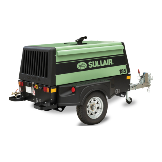
Portable Air Compressor
SAFETY WARNING
Users are required to read the
entire User Manual before han-
dling or using the product.
USER MANUAL
185
Tier 4 Final
Kubota
WARRANTY NOTICE
Failure to follow the instructions
and procedures in this manual,
or misuse of this equipment, will
void its warranty.
Subject to EAR, ECCN EAR99 and related export control restrictions.
PART NUMBER:
02250216-781 R02
The information in this manual is current as of its
publication date and applies to compressor models
indicated on this cover with serial number:
201507170000
and all subsequent serial numbers.
Publication date: 08/31/2018
Copyright © 2018 Sullair, LLC. All rights reserved.
Advertisement
Table of Contents

Related Manuals for Sullair 185CFM


Summary of Contents for Sullair 185CFM
- Page 1 Publication date: 08/31/2018 void its warranty. Copyright © 2018 Sullair, LLC. All rights reserved. Subject to EAR, ECCN EAR99 and related export control restrictions.
- Page 2 Sullair training courses provide hands-on and classroom instruction for the proper operation, maintenance, and servicing of Sullair products. Individual courses on Portable compressors are offered at regular intervals throughout the year at Sullair’s training facility located in Michigan City, Indiana and on-site at Sullair distributor locations.
-
Page 3: Table Of Contents
2.15 Symbols and references........................ 14 Section 3: Description....................19 Introduction............................ 19 Description of components ......................19 Sullair compressor unit, functional description ................19 Compressor cooling and lubrication system, functional description ..........19 Compressor discharge system, functional description ..............21 Capacity control system, functional description................22 3.6.1... - Page 4 Table of Contents 185 T4F Kubota User Manual 3.13 Electrical system, functional description..................34 Section 4: Specifications..................35 Specifications—49HP 185 Kubota ....................35 Lubrication guide—compressor..................... 36 Lubrication guide—engine......................36 Application guide ........................... 37 Identification—DPQ........................38 Identification—DLQ ........................40 Section 5: Operation ....................43 General............................
-
Page 5: Section 2: Safety
2.1 General protective clothing, protective shields and barriers Sullair designs and manufactures all of its products so they and electrical protective equipment, as well as noise can be operated safely. However, the responsibility for safe... -
Page 6: Fire And Explosion
2: Safety 185 T4F Kubota User Manual E. Provide an appropriate flow-limiting valve for each cap slowly to its stop to relieve any excess pressure additional 75 feet (23 m) of hose in runs of air hose and make sure coolant is not boiling before removing exceeding 1/2″... -
Page 7: Moving Parts
185 T4F Kubota User Manual 2: Safety replaced immediately to prevent accumulation of liq- operating in ambient temperatures above 60°F uids or fluid film within the material. DO NOT use (16°C). flammable solvents for cleaning purposes. P. DO NOT attempt to use ether as a starting aid in gas- E. -
Page 8: Hot Surfaces, Sharp Edges And Sharp Corners
2: Safety 185 T4F Kubota User Manual B. DO NOT attempt to operate the compressor with the Standards 29 CFR 1920 and any other Federal, State fan, coupling or other guards removed. or Local codes or regulations. C. Wear snug-fitting clothing and confine long hair when working around this compressor, especially when DANGER exposed to hot or moving parts. -
Page 9: Electrical Shock
185 T4F Kubota User Manual 2: Safety pound to air line anti-icer systems. Keep openings of 2.8 Electrical shock valve or atomizer tube of ether starting aid system A. Keep the towing vehicle or equipment carrier, com- pointed away from yourself and other personnel. pressor hoses, tools and all personnel at least 10 J. -
Page 10: Entrapment
2: Safety 185 T4F Kubota User Manual Keep lift operator in constant attendance whenever reservoir tanks. Lockout or tag lines or compressor is suspended. valves. b. Any mechanism under tension or pres- J. Set compressor down only on a level surface capa- sure, such as springs, should be ble of supporting at least its net weight plus an addi- released and locked out or tagged. -
Page 11: Jump Starting
185 T4F Kubota User Manual 2: Safety made to inform him or her that the lock- J. Set the parking brakes of both the compressor (if pro- out or tagout device has been removed. vided) and the starting vehicle or otherwise block both sides of all wheels. -
Page 12: Towing1
2: Safety 185 T4F Kubota User Manual U. Allow the compressor to warm up. When the com- device or otherwise couple the compressor to the pressor is warm and operating smoothly at normal towing vehicle. idle RPM, disconnect the jumper cable from the engine block in the compressor, then disconnect the WARNING other end of this same cable from the grounded neg-... -
Page 13: Towing
185 T4F Kubota User Manual 2: Safety M. Make sure parking brakes in towing vehicle are set, CAUTION or that its wheels are chocked or blocked, or that it is otherwise restrained from moving. Then, release the compressor parking brakes, if provided. Retract the front screw jack only after attaching the compressor to the tow vehicle. -
Page 14: Parking Or Locating Compressor
2: Safety 185 T4F Kubota User Manual ing forward or backing up, regardless of the terrain contact has sufficient load bearing capability to sup- being traversed. port the weight of the compressor. DO NOT permit personnel to ride in or on the com- pressor. -
Page 15: California Proposition 65
185 T4F Kubota User Manual 2: Safety K. Move the towing vehicle well clear of the parked 2.14 California proposition 65 compressor and erect hazard indicators, barricades and/or flares (if at night) if compressor is parked on or adjacent to public roads. Park so as not to inter- WARNING fere with traffic. -
Page 16: Symbols And References
2: Safety 185 T4F Kubota User Manual 2.15 Symbols and references The symbols below may or may not be used. Please refer to the decals set forth on the machine for applicable sym- bols. DIESEL FUEL HEARING PROTECTION ROTARY COMPRESSOR HARD HAT TEST RUN DRAIN... - Page 17 185 T4F Kubota User Manual 2: Safety ENGINE START DANGEROUS OUTLET ENGINE ECM REMOTELY CONTROLLED READ/WRITE DATA CORROSIVE INTAKE AIR EXHAUST GAS WARNING FAN GUARD DO NOT MAINTENANCE BELT GUARD BELOW TEMPERATURE DO NOT TOW SERVICE POINT BAR/PSI LOW TEMPERATURE BATTERY STD AIR BATTERY DISCONNECT...
- Page 18 2: Safety 185 T4F Kubota User Manual RADIATOR HOUR METER COMPRESSOR AIR AIR-CIRCULATING PRESSURE START AIR-COOLED OIL COOLER CONTROL LIQUID-COOLED OIL COOLER ENGINE PREHEAT LOW TEMP AID LUBRICATION ENGINE WARNING TRAILER TOWING MODE FUEL LEVEL AXLE ENGINE RPM LUBRICANT GREASE ENGINE OIL EXAMINE, CHECK PRESSURE...
- Page 19 185 T4F Kubota User Manual 2: Safety DO NOT OPERATE WATER DRAIN WHILE STACKED PRESSURIZED SPRING SEVER (FAN) DO NOT MIX FLUIDS DEF FLUID ONLY AUTO START/STOP FLUID DRAIN LOW FUEL HEST: HIGH EMISSIONS DPF: DIESEL SYSTEM TEMPERATURE PARTICULATE FILTER EMISSIONS DPF REGEN.
- Page 20 2: Safety 185 T4F Kubota User Manual Notes: 02250216-781 R02 Subject to EAR, ECCN EAR99 and related export control restrictions.
-
Page 21: Section 3: Description
Compared to other com- compressor unit where it mixes directly with the air as the pressors, Sullair’s are unique in terms of reliability and rotors turn. The fluid flow has three main functions: durability. Compressor internal components require no routine maintenance inspections. - Page 22 3: Description 185 T4F Kubota User Manual 1. Minimum pressure/check valve 10. Fuel tank 2. Engine air filter 11. Compressor air filter 3. Coolant overflow bottle 12. Thermal valve/compressor fluid filter 4. Radiator/fluid cooler assembly 13. Battery 5. Fuel/water separator 14.
-
Page 23: Compressor Discharge System, Functional Description
The fluid functional description flows through the fluid filter and on to the compressor unit Refer to Figure 3-2 on page 21. The Sullair compressor bypassing the cooler. As the compressor continues to unit discharges a compressed air/fluid mixture into the operate, the temperature of the fluid rises and the ther- receiver tank. -
Page 24: Capacity Control System, Functional Description
3: Description 185 T4F Kubota User Manual 1. Receiver tank 4. Compressor unit 2. Minimum pressure/check valve 5. Service air outlets 3. Internal air/oil separator element Figure 3-3: Compressor discharge system separate and fall to the bottom of the receiver tank. The set to open if the receiver tank pressure exceeds small amount of fluid remaining in the compressed air 200 psig (13.8 bar). -
Page 25: Start-0 To 58 Psig (0 To 4.0 Bar)
185 T4F Kubota User Manual 3: Description nents of the compressor. The functional descriptions of 3.6.3 Modulation—100 to 125 psig (6.9 to the control system are described by relating them to four 8.6 bar) distinct phases of operation. They apply to any control If the demand on the compressor is less than its rated system with the exception of those with specified pres- capacity, the service line pressure will rise above... -
Page 26: Piping And Instrumentation-Compressor System
3.7 Piping and instrumentation—compressor system 02250210-170 R02 (sh1) - Page 27 3.7 Piping and instrumentation—compressor system Components Key Description Component Description FILTER, AIR RECIEVER TANK TEMPERATURE SWITCH GAUGE, FILTER RESTRICTION (OPTONAL) DRY SIDE SERVICE PRESSURE INLET VALVE COMPRESSOR SWITCH, TEMPERATURE VALVE, RELIEF RECEIVER, AIR/OIL GLASS, SIGHT OIL LEVEL VALVE, MINIMUM PRESSURE/CHECK VALVE, BALL ORIFICE VALVE, BLOWDOWN N.C.
-
Page 28: Piping And Instrumentation-Engine System
3.8 Piping and instrumentation—engine system 02250210-170 R02 (sh2) - Page 29 3.8 Piping and instrumentation—engine system Components Key Description Component Description TURBOCHARGER, COMPRESSOR FUEL LEVEL COOLANTFILL OIL LEVEL (DIPSTICK) OVERFLOW BOTTLE OIL PRESSURE FUEL LEVEL SENDER W/SWITCH (OPTIONAL) COOLANT TEMPERATURE SENSOR RAIN CAP, EXHAUST SYSTEM FUEL FILTER W/ WATER SEPARATOR FUEL INJECTION PUMP ELECTRIC FUEL PRIMING PUMP FILTER, FUEL FUEL TANK CAP W/VENT...
-
Page 30: Air Inlet System, Functional Description
3: Description 185 T4F Kubota User Manual 9. The inhibit lamp indicates that regeneration 3.9 Air inlet system, functional is inhibited. See Section 3.11: Engine description exhaust after-treatment on page 30. The air inlet system consists of two air filters, a compres- 10. - Page 31 185 T4F Kubota User Manual 3: Description 1. Master gauge 9. Inhibit lamp 2. LCD display 10. Compressor warning lamp 3. User interface buttons 11. Engine warning lamp 4. Active regeneration lamp 12. START/ON/OFF switch 5. Regeneration needed / request lamp 13.
-
Page 32: Engine Exhaust After-Treatment
Your Sullair compressor’s engine exhaust regenerates in catalyst (DOC) and a diesel particulate filter (DPF). The one of several different ways, depending on the com- exhaust flows from the engine through the DOC and then pressor’s operating conditions. - Page 33 185 T4F Kubota User Manual 3: Description Table 3-1: Engine exhaust regeneration lamp sequence Active Regeneration Inhibit regeneration needed / lamp lamp request lamp Engine lamps Particulate level Active/Parked regeneration Regeneration not needed Level 0: Passive regeneration only Regeneration not needed Active regeneration needed SOLID LIGHT Level 1: Active regeneration...
-
Page 34: Wiring Diagram
3.12 Wiring diagram 02250214-326(r12) - Page 35 3.12 Wiring diagram Drawing notes TO BATTERY POSITIVE TO BATTERY SIDE OF DISCONNECT SWITCH ISO 280 relay socket (bottom view) COIL+ COIL- Cooper/Bussmann 15303-4-0-4S RTMR power distribution module KEYSWITCH ALTERNATOR GLOW PLUG RELAY IGNITION SWITCH 226A GLOW PLUGS START RELAY START SWITCH 216A EGR RELAY...
-
Page 36: Electrical System, Functional Description
3: Description 185 T4F Kubota User Manual pressor discharge temperature switch that will shut the 3.13 Electrical system, functional compressor down if the compressor temperature description exceeds 250°F (121°C). The single axle controller will The electrical system consists of the basic electrical ele- shut the compressor down if the engine speed falls below ments required to operate the compressor and also has a 1300 rpm and an optional low fuel level switch shuts... -
Page 37: Section 4: Specifications
185 T4F Kubota User Manual 4: Specifications Section 4 Specifications 4.1 Specifications—49HP 185 Kubota Table 4-1: Package specifications Table 4-2: Compressor specifications Model series 49HP 185 Model series 49HP 185 Type Rotary screw Package 2175 1950 Working weight Actual delivery /min 1960 1740... -
Page 38: Lubrication Guide-Compressor
® 1 Sullair AWF 1500 -20 to 120 -29 to 49 Model KUB1803 (T4F) Sullair AWF part numbers: 250030-757 (5 gallons/18.9 liters) and 250030-758 (55 gallon/208 liter drum) Emissions level U.S. EPA Tier 4 final Operating speed 2720 4.3 Lubrication guide—engine... -
Page 39: Application Guide
(for example, the ambient temperature is outside the recommended temperature range for Sul- lair AWF). Sullair encourages users to participate in a fluid analysis program. The analysis might indicate a need for change intervals different from those recommended in this man- ual (for example, to maximize the life of the machine in dirty environments). -
Page 40: Identification-Dpq
4.5 Identification—DPQ 02250214-081 R02... - Page 41 4.5 Identification—DPQ Drawing notes DIMENSIONS ARE IN INCHES. [ ] DIMENSIONS ARE IN MILLIMETERS. REFERENCE: A STANDARD CONTAINER SIZE IS 92" WIDE X 94" TALL X 232" LONG. ALL DIMENSIONS ARE +/- .50" [12.7mm] ENGINE COOLANT DRAIN FLEXIBLE HOSE ENGINE OIL DRAIN FLEXIBLE HOSE COMPRESSOR OIL DRAIN LIFTING BAIL EYE (APPROX.
-
Page 42: Identification-Dlq
4.6 Identification—DLQ 02250224-015 R00... - Page 43 4.6 Identification—DLQ Drawing notes DIMENSIONS ARE IN INCHES. [ ] DIMENSIONS ARE IN MILLIMETERS. REFERENCE: A STANDARD CONTAINER SIZE IS 92" WIDE X 94" TALL X 232" LONG. ALL DIMENSIONS ARE +/- .50" [12.7mm] ENGINE COOLANT DRAIN FLEXIBLE HOSE ENGINE OIL DRAIN FLEXIBLE HOSE COMPRESSOR OIL DRAIN LIFTING BAIL EYE (APPROX.
- Page 44 4: Specifications 185 T4F Kubota User Manual Notes: 02250216-781 R02 Subject to EAR, ECCN EAR99 and related export control restrictions.
-
Page 45: Section 5: Operation
Thermal valve Functions as a temperature regulator by directing the com- While Sullair has built into this compressor a complete pressor fluid either to the cooler or to the compressor unit. set of controls and indicators that allow the operator to control and monitor the compressor’s operation and per-... -
Page 46: Shutting Down The Compressor
If an emergency shutdown is required, immedi- segments for one second, off for one ately press the emergency stop button. second, and then display the Sullair Do not use the emergency stop button in place logo followed by the software prod- of the normal shutdown procedure described uct number with revision level. -
Page 47: Section 6: Maintenance
6.2 Engine coolant requirement for radiators NOTE The coolant provided with Sullair portable air compres- sors is ethylene glycol based, 50/50 mixture, and should Dispose of fluids in accordance with applicable never be mixed with a different coolant type, color or federal, state and local regulations. -
Page 48: Maintenance Every 50 Hours
6.8 Maintenance every 1500 hours • Change the compressor fluid with new Sullair 6.9.3.1 Air filter replacement ® and replace the fluid filter element. (See 1. -
Page 49: Separator Element Replacement
185 T4F Kubota User Manual 6: Maintenance 1. Fluid filter 1. Filter body 2. Compressor unit 2. Filter cover 3. Thermal valve manifold 3. Primary element Fluid filter replacement P/N: 250028-032 4. Safety element (optional) Air filter primary element replacement P/N: 02250102-158 Figure 6-1: Compressor fluid filter Air filter safety element replacement P/N: 02250102-160 Figure 6-2: Air filter... -
Page 50: Fuel/Water Separator Maintenance
6: Maintenance 185 T4F Kubota User Manual 1. Disconnect all receiver tank cover piping connections to permit removal (return line, service line, etc.). 2. Remove the fluid return line from the fitting on the cover. 3. Remove the eight (8) cover bolts and wash- ers and lift the cover off the receiver tank. -
Page 51: Replacing The Fuel Filter Of The Fuel/Water Separator
185 T4F Kubota User Manual 6: Maintenance 2. Open the compressor canopy. 3. Remove the separator bowl by turning it to the left. 4. Remove the old fuel filter by turning it to the left. 5. Install the new fuel filter by turning it to the right until tight. - Page 52 Section 4.1: Specifications—49HP 185 will cause coupling and/or compressor failure. Kubota on page 35 or can be obtained by contacting a Sullair representative. 2. Adjust the pressure regulator so that the The following procedure applies to a compressor with compressor maintains 115 psig (8 bar).
-
Page 53: Bearing Lubrication
185 T4F Kubota User Manual 6: Maintenance flows back to the outer bearing, and then back out of the 6.9.8 Bearing lubrication grease cap hold (see Figure 6-6). Refer to Figure 6-6. Proper lubrication of the portable compressor’s bearing axle is critical to its proper function 1. -
Page 54: Troubleshooting
If the troubleshooting remedy does not work, or the mal- prevent additional damage or abnormal operation. function is not covered in this troubleshooting chart, con- tact your nearest Sullair representative or Sullair for technical assistance. Always: Table 6-1: Troubleshooting guide... - Page 55 185 T4F Kubota User Manual 6: Maintenance Table 6-1: Troubleshooting guide Symptom Probable cause Remedy Faulty engine temperature sensor Check wiring connection to the sensor Clean cooler and check for proper ventila- Cooling air flow is insufficient tion Loose or broken fan belt Tighten or replace belt High engine tempera- Fill with proper water/glycol mixture as...
- Page 56 6: Maintenance 185 T4F Kubota User Manual Table 6-1: Troubleshooting guide Symptom Probable cause Remedy Pressure regulating valve is set too Readjust high Check control lines Control system leak causing loss of Defective pressure regulating valve. Repair pressure signal valve (kit available) Improper unloading with an excessive Inlet valve jammed...
-
Page 57: Section 7: Noise Control
7.1 Noise emissions warranty mate purchaser or while it is in use. Sullair warrants to the ultimate purchaser and each sub- 2. The use of the compressor after such device sequent purchaser that this air compressor was... -
Page 58: Noise Emissions Maintenance And Maintenance Record Log
7: Noise Control 185 T4F Kubota User Manual 7.3 Noise emissions maintenance and maintenance record log The following instructions and maintenance record log book, for the proper maintenance, use and repair of this com- pressor, is intended to prevent noise emission degradation. Table 7-1: Annual muffler and exhaust system inspection At least annually inspect muffler(s) and engine exhaust system to make sure all parts are securely mounted, that all joints and connections are tight, and that the muffler is in good condition. - Page 59 185 T4F Kubota User Manual 7: Noise Control Table 7-3: Annual engine vibration mount inspection At least annually inspect engine vibration mounts for security of attachment and to make sure the resilient parts are intact. Do not operate compressor with defective engine mounting system. Remove and replace defective parts by ordering with part numbers indicated in Parts List.
- Page 60 7: Noise Control 185 T4F Kubota User Manual Table 7-5: Annual acoustical materials inspection At least annually inspect all acoustical materials, if any, for security of attachment. Make sure that there is not any material missing or damaged (refer to Parts List). Clean or replace, if necessary. Do not operate compressor with defective acoustical material.
- Page 61 WARNING Breathing diesel engine exhaust exposes you to chemicals known to the State of California to cause cancer and birth defects or other reproductive harm. • Always start and operate the engine in a well-ventilated area. • If in an enclosed area, vent the exhaust to the outside. •...
- Page 62 Sullair, LLC 3700 East Michigan Boulevard Michigan City, IN 46360 USA www.sullair.com 1-800-SULLAIR (USA only) 1-219-879-5451 (non-USA) Information and specifications are subject to change without prior notice. Subject to EAR, ECCN EAR99 and related export control restrictions.
Need help?
Do you have a question about the 185CFM and is the answer not in the manual?
Questions and answers