Table of Contents
Advertisement
Quick Links
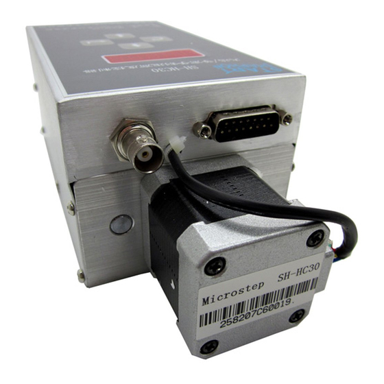
Microstep
SH-HC30
Flame / Plasma Cutting Torch
Height Controller
System Manual
SH-HC30 Height Controller System Manual
Manual Content
1. Foreword
2. Overview
3. Installation
4. Fast Operation
5. Debugging
6. Operating guide
7. Control Panel
8. Troubleshooting
9. Initial positioning
10. NC and commands related with
height adjustment device
11.
Height
adjustment
controller
remote
1
Advertisement
Table of Contents

Subscribe to Our Youtube Channel
Related Manuals for MicroStep SH-HC30


Summary of Contents for MicroStep SH-HC30
- Page 1 SH-HC30 Height Controller System Manual Manual Content Microstep 1. Foreword 2. Overview SH-HC30 Flame / Plasma Cutting Torch 3. Installation Height Controller 4. Fast Operation System Manual 5. Debugging 6. Operating guide 7. Control Panel 8. Troubleshooting 9. Initial positioning 10....
- Page 2 SH-HC30 Height Controller System Manual Graphic model of height controller All rights reserved Forbidden to transmit or copy any files for the purpose of commercial, telecommunication and others without particular permission. Compensation should be paid if any clause is violated. All rights belong to the company.
-
Page 3: Table Of Contents
SH-HC30 Height Controller System Manual Contents 1. Preface ............................ 1 1.1 Purpose..........................1 1.2 Important statement:......................1 1.3 Warning ..........................2 1.4 Terms..........................2 1.5 Company Information ....................... 3 2. Overview ..........................3 2.1 Technical Features ......................3 2.2 Main Technical Parameters ....................4 3. - Page 4 SH-HC30 Height Controller System Manual 6.1 Initial debugging of capacitive detection ................ 21 6.2 Debugging steps of a key height calibration ..............22 7 Controller Panel ........................22 7.1 Control Parameters ......................22 7.2 Operation Panel ....................... 23 7.3 Description of Display...................... 24 8 Troubleshooting........................
-
Page 5: Preface
Beijing Start Microstep Control Technology Co., Ltd. SH-HC30 flame / plasma cutting torch height controller is easy to use; debugging is convenient; and the price is low; it inherits the characteristics of Microstep products: "The performance of imported product;... -
Page 6: Warning
All the responsibilities will be undertaken by the users if any particular illegal utilization of SH-HC30 flame / plasma cutting torch height controller or manual is made for it doesn’t represent our position and we refuse to admit the legal responsibility. -
Page 7: Company Information
SH-HC30 Height Controller System Manual One key height calibration: when the capacitance height measurement is adopted, the specific inductive capacity between the capacitance detection ring and the cutting board may affect the accuracy of height measurement due to temperature, pressure, humidity, gas composition and many other factors on site. -
Page 8: Main Technical Parameters
Stepper motor instead of the traditional DC motor SH-HC30 flame / plasma cutting torch height controller uses the unique stepper motor control technology of Start Microstep Company. It subverts the traditional DC motor height control mode and makes it become fast and smooth, and the life of the product is increased greatly. -
Page 9: Installation
SH-HC30 Height Controller System Manual Total weight of Arc Voltage height: 1.645kg Detection system: capacitance-type detector, arc voltage height detector 3. Installation 3.1 Mechanical Installation The name and position of relevant components of the height controller are shown in Figure 3-1. - Page 10 SH-HC30 Height Controller System Manual Note: Pay attention to the depth of six mounting holes in installation so as not to affect the stroke. 2. The distance from the shell of the height controller to the interior should be less than...
- Page 11 SH-HC30 Height Controller System Manual Figure 3-4 Back view of height controller Installation diagram of the connecting components of the height controller is shown in Figure 3-5 Figure 3-5 Installation diagram of the connecting components of the height controller Page 7...
-
Page 12: Electrical Installation Connection
SH-HC30 Height Controller System Manual Electrical Installation Connection 3.2.1 External Switch Control Mode The external switch control mode is applicable to the capacitance height control and arc voltage height control K1 Manual and automatic switching K2 Manual rise K3 Manual falling ... - Page 13 SH-HC30 Height Controller System Manual Figure 3‐6 capacitive controller electrical installation diagram Note: The diameter of 24 V power wire and ground wire should be larger than 0.75 mm2 Manual and automatic switching Manual rise Manual falling Ground Page 9...
- Page 14 SH-HC30 Height Controller System Manual Table 3-1 25-pin connector of numerical control system for the pin definition of the height control system Property Description Output Manual / automatic selective signal Power Supply Power supply 24V ground, height controller power supply...
- Page 15 SH-HC30 Height Controller System Manual 25-pin connector and 9-pin connector see Table 3-1, Table 3-2 and Table 3-3 Plasma Power Supply Height controller Voltage divider board back of numerical control system Figure 3-8 Electrical installation diagram of arc voltage controller...
- Page 16 SH-HC30 Height Controller System Manual Note: Those that do not list the pin serial number will not be used Connecting to voltage divider boar Connecting to numerical control system Connecting to height controller 9‐pin connector of voltage divider board 15‐pin connector of height 25‐pin connector of numerical control system Figure 3-9 Wiring diagrams of arc-type height controller, voltage divider board and numerical control system Note: The wire diameter of 24V power cord and ground wire should be greater than 0.5 square millimeter.
- Page 17 SH-HC30 Height Controller System Manual The electrical installation diagram of height controller when the arc voltage detection and the capacitive detection are used together. Plasma Power Supply Arc voltage signal 15-pin High-frequen 分压板 9 芯接头 back of numerical control Height controller ...
-
Page 18: Description Of Functions Of Voltage Divider Board
SH-HC30 Height Controller System Manual Automatic open Arc voltage signal Manual rise Manual falling 24V GND This figure is kept on standby – automatic connecting method by using arc voltage and capacitance 3.2.3 The control mode of communication interface of CNC system... - Page 19 SH-HC30 Height Controller System Manual J3 AC power, connecting device J2 arc voltage input, arc p voltage AC220V power supply terminal connecting to the plasma power supply J1 arc voltage output of voltage divider board, connecting to the height controller...
-
Page 20: Dimensional Drawing Of Voltage Divider Board
SH-HC30 Height Controller System Manual Note: Those without pin number will not be used. Table 3-5 The pin definition of J2 connector Property Description Power supply Ground Plasma arc voltage positive terminal (clip for connecting with Input steel plate) -
Page 21: Quick Operation Guide For Capacitance And Arc Voltage Height Controller
SH-HC30 Height Controller System Manual 4. Quick Operation Guide for Capacitance and Arc Voltage height Controller 4.1 The control operation of electrical operation panel: (external switch mode) For the wiring of electrical connection of capacitance height control see the "Electrical Connection"... -
Page 22: Sh-2002Ah/Sh-2200H Cnc System Output Interface Operation (I / O Control Mode)
SH-HC30 Height Controller System Manual Now the mechanical lift device of the height controller realizes the automatic height control. If the height of the cutting gun is inappropriate, repeat the above steps 1-3. In automatic mode, the up / down switch of the cutting gun does not work. -
Page 23: The Communication Interface Of The Cnc System Is Used To Complete The Operation (Rs232 Communication Mode)
SH-HC30 Height Controller System Manual Usually, I / O of the numerical control system is in the manual control mode of the height controller. When the processing starts, I / O of the numerical control system converts to the automatic control mode of the height controller. -
Page 24: Operation Flow Of Daily Work
SH-HC30 Height Controller System Manual 4.5 Operation Flow of Daily Work Flow starts numerical control system height controller power-on auto-detection of "manual /auto" status Yes No Manual signal The cutting torch adjusts the When the manual rise is low level, the cutting... -
Page 25: Operating Guide
SH-HC30 Height Controller System Manual 5. Operating Guide After turn-on, the height controller has three states: manual, automatic and parameter editing states. 5.1 Parameter Setting In the manual or automatic mode, press the key “Enter” for a long time, enter the parameter editing ... -
Page 26: Debugging Steps Of A Key Height Calibration
SH-HC30 Height Controller System Manual When the capacitive height measurement is adopted, the specific inductive capacity (SIC) between the capacitance detection ring and the cutting board may affect the height measurement accuracy due to the temperature, pressure, humidity, gas composition and many other factors on site. In addition, the serious non-linear relationship exists between the capacitance value and the height value. -
Page 27: Operation Panel
SH-HC30 Height Controller System Manual Selection of detector (C: capacitance): 0 is the arc voltage detection; 1 is capacitive detection. For the set range and factory value see Table 7-1. No board drop parameter (b): In the capacitive detection mode, when the detected height is higher than value b, the cutting torch stops;... -
Page 28: Description Of Display
SH-HC30 Height Controller System Manual Enter key: enter or exit the editing state. Function key: in the manual state, implement the function of “a key height calibration”; in the editing state, switch the current editing parameters. Up arrow: in manual and automatic state, the set height value plus 1; in the editing state, the current parameter plus one. -
Page 29: Troubleshooting
SH-HC30 Height Controller System Manual arc voltage mode, there is no decimal point position; unit: V. The first one is described as follows: H: the upper limit value. When the height is larger than this value, it is the ... -
Page 30: Description Of Initial Positioning Function
SH-HC30 Height Controller System Manual 9. Description of initial positioning function 9.1 Positioning mode The impact position switch is set in the height controller. When the cutting gun moves down and collides with the cut workpiece, the internal switch is turned on without the need of special cutting gun and "protection cap". -
Page 31: Command Functions Related To M Of Cnc System And Height Controller
SH-HC30 Height Controller System Manual manual mode of plasma, the height controller carries out the manual starting arc perforation, after perforation, the cutting gun moves (through the numerical control system ) for actual cutting, at this time, the value on the nixie tube display of the height controller is the actual arc voltage of the plasma power supply in the current environment. -
Page 32: Height Adjustment Remote Controller
SH-HC30 Height Controller System Manual 1. Close the cutting oxygen (M13); 2. Turn off the height controller (M39); 3. The cutting gun rises (M70); The plasma cutting operation sequence is as follows: 1. Turn off the arc voltage switch; 2. Turn off the height controller (M39);... -
Page 33: Function Introduction
SH-HC30 Height Controller System Manual Graphic model of remote controller Figure X‐1 Outside view of the height adjustment remote controller The remote controller uses the computer core design and can implement the information communication RS232 with the master controller. The adjustment of the height and the sensitivity adopts the simple knob design so that it has the operation conveniences of analog circuit and accuracy and reliability of digital circuit. -
Page 34: Wiring Instructions
SH-HC30 Height Controller System Manual When it is powered on, the controller is in manual operation state, the indicator light "Manual" is on, while the indicator light "automatic” is off. At this time, if the height of the cutting torch needs to be adjusted, the button of "up" or "down" may be pressed. -
Page 35: Installation Dimensions
SH-HC30 Height Controller System Manual Table X-1 Function definition of the back terminal of the controller Property Description Power supply Power supply 24V ground, height controller power supply Input RS232 communication receiving terminal Input RS232 communication receiving terminal Power supply...
Need help?
Do you have a question about the SH-HC30 and is the answer not in the manual?
Questions and answers