Advertisement
Quick Links
Advertisement

Subscribe to Our Youtube Channel
Related Manuals for ADAPT SOLUTIONS SPEEDY-LIFT SP-CHR17L


Summary of Contents for ADAPT SOLUTIONS SPEEDY-LIFT SP-CHR17L
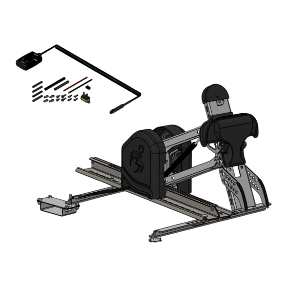
- Page 1 SPEEDY-LIFT INSTALLATION MANUAL SP-CHR17L CHRYSLER PACIFICA DRIVER SIDE 2017 & UP...
- Page 2 Nylon Insert Locknut 1/4-20 Thin PRD 337-211P Button Head Socket Cap Screw Zinc Plated 5/16-18 x 1/2 PRD 2946 Flange Locknut Zinc Plated 5/16-18 PART NUMBER SP-CHR17L DESCRIPTION 1 of 5 Speedy-Lift 2 Kit -Left- SCALE 1:5 |tech@adaptsolutions.ca|866.641.0419|418.889.9838 fax ADAPT SOLUTIONS...
- Page 3 Flat Washer Zinc Plated I.D. 3/8 USS PRD 341-146P Flat Washer Zinc Plated I.D. 11/32 SAE 5/16 PRD 2945 Flange Locknut Zinc Plated 3/8-16 SCALE 1:5 PART NUMBER SP-CHR17L DESCRIPTION Speedy-Lift 2 Kit -Left- 2 of 5 |tech@adaptsolutions.ca|866.641.0419|418.889.9838 fax ADAPT SOLUTIONS...
- Page 4 Hex Cap Bolt Zinc Plated 1/4-20 x 1/2 G5 PRD 333-105M Nylon Insert Locknut 1/4-20 Thin PRD BSHCS51618114P Button Head Socket Cap Screw Zinc Plated 5/16-18 x 1 1/4 SCALE 1:9 SCALE 1:5 PART NUMBER SP-CHR17L DESCRIPTION Speedy-Lift 2 Kit -Left- 3 of 5 |tech@adaptsolutions.ca|866.641.0419|418.889.9838 fax ADAPT SOLUTIONS...
- Page 5 KIT SPEEDY-LIFT 2 CHRYSLER PACIFICA 2017+ SP700B Hook Assembly -Black- PRD 337-211P Button Head Socket Cap Screw Zinc Plated 5/16-18 x 1/2 SCALE 1:6 SCALE 1:5 PART NUMBER SP-CHR17L DESCRIPTION 4 of 5 Speedy-Lift 2 Kit -Left- |tech@adaptsolutions.ca|866.641.0419|418.889.9838 fax ADAPT SOLUTIONS...
- Page 6 PRD 337-211P Button Head Socket Cap Screw Zinc Plated 5/16-18 x 1/2 PRD 2946 Flange Locknut Zinc Plated 5/16-18 SCALE 1:6 SCALE 1:4 PART NUMBER SP-CHR17L SCALE 1:4 DESCRIPTION Speedy-Lift 2 Kit -Left- 5 of 5 |tech@adaptsolutions.ca|866.641.0419|418.889.9838 fax ADAPT SOLUTIONS...
- Page 7 NOTE: If installing a LINK with a SPEEDY-LIFT, install the LINK floor adapter brakets at the same time. 1. Stow the second row seats. Install the provided brackets # SL-CHR17-04 and # SL-CHR17-05 using the four provided 5/16-18x3/4 bolts, nuts and washers. Align the protruding bolt with the hole in the stow and go cover, then tighten down all the bolts.
- Page 8 3. Remove the rear cover of the stow and go mecanisme to gain access to the seat attachement bolts. Remove the left hand bolt of the two central bolts and install the bracket # SL-CHR17L-03 aligning with the slot then tighten down. 4.
- Page 9 5. Two coresponding holes will now have to be driled 3/8 diameter in the rear cover to allow the bolts to pass through. For the center hole, use the provided stencil. For the exterior hole cut off the plastic clip and drill the hole directly through the center of the clip.
- Page 10 6. Install the exterior SPEEDY-LIFT floor bracket # SL-CHR17L-01 and the interior floor bracket # SL- CHR17-02 using the provided 3/8 nuts and flat washers. 7. Place the SPEEDY-LIFT in the vehicle on the floor adaptors using the plastic shims between the SPEEDY-LIFT and the floor adapters.
- Page 11 8. The SPEEDY-LIFT up/down and in/out motors can be disengaged manualy to slide the SPEEDY- LIFT in and out and move the arm up and down. NOTE: When disengaging the arm it will spring up as the arm of the SPEEDY-LIFT is aided by a 100-lb gas shock, so hold the arm firmly while disengaging. To disengage, move the handle to the right and push down.
- Page 12 10. Install the electrical wiring for the SPEEDY-LIFT. Follow the instructions found in the attached document entitled: ELECTRICAL INSTALLATION FOR SPEEDY-LIFT. 11. Power the SPEEDY-LIFT all the way out. Attach the wheelchair hook and support assembly SP700 to the head of the SPEEDY-LIFT. The height of the hook assembly may need to be adjusted depending on the height or style of the wheelchair.
- Page 13 13. Press the ‘OUT’ button on the hand held pendant until the upper wheelchair support bracket is positioned 1/4” to 1/2” below the rigidizer bar on the wheelchair. Adjust the stop down bolt so that the arm stops in this position. 14.
- Page 14 15. Adjust the locking mechanism. Remove the wheelchair from the SPEEDY-LIFT. Press and hold the ‘IN’button until the SPEEDY-LIFT is in its full up position. While holding the lock closed, pull the cable tight and secure the cable lock. Cut off the excess lenght of cable. Test slowly to see if the locking mechanism operates properly.
-
Page 15: Warning Decals
WARNING DECALS After completing the installation of the SPEEDY LIFT, please take time to install the warning decals. NOTE: The surface must be clean, dry and at ambient temperature for the sticker to stick to the surface. Start by locating a position to install the decals. ... -
Page 16: Troubleshooting
TROUBLESHOOTING PROBLEM POSSIBLE CAUSES Bad electrical connections. Check and clean corrosion from all connections including the car’s battery cable connections. Hand pendant wire problem. Check hand pendant wire to make sure it is plugged in properly. Check the wire for any cuts. If so, replace the wire. - Page 17 ELECTRICAL INSTALLATION FOR SPEEDY-LIFT 1. Thread the lead power cable (red +) under the doorstep molding and through the firewall. WARNING: Pass through a grommet in the firewall to prevent the cable from chaffing. 2. Install the circuit breaker near the battery and then connect the battery to the circuit breaker.
- Page 18 ELECTRICAL BOX CONNECTIONS ASENTO SPEEDY LIFT with...
- Page 19 SPEEDY LIFT ALONE SPEEDY LIFT CORD RED = 12 V POWER SUPPLY BLACK = GROUNDED TO THE CHASSIS...
-
Page 20: Year Limited Warranty
The only remedy for a defect in one of Adapt Solutions products shall be the repair or the replacement, at the discretion of Adapt Solutions, of the defective part or component. If repair or replacement is not commercially practical or cannot be timely made, Adapt Solutions may decide to refund the purchase price of the equipment (XL-BASE;...
Need help?
Do you have a question about the SPEEDY-LIFT SP-CHR17L and is the answer not in the manual?
Questions and answers