
Related Manuals for Cypress FM4-216-ETHERNET


Summary of Contents for Cypress FM4-216-ETHERNET
- Page 1 FM4-216-ETHERNET Hardware V1.0 / Documentation V1.3 Document Number: 002-09877 Rev. *B SHOW TITLE MM/DD/YY...
- Page 2 (“Unintended Uses”). A critical component is any component of a device or system whose failure to perform can be reasonably expected to cause the failure of the device or system, or to affect its safety or effectiveness. Cypress is not liable, in whole or in part, and you shall and hereby do release Cypress from any claim, damage, or other liability arising from or related to all Unintended Uses of Cypress products.
-
Page 3: Table Of Contents
Overview ▪ Features, Board Features & Contents ▪ Test it ▪ The Hardware ▪ The Jumper Table Jumper Default ▪ Board Power ▪ Software Examples & Tools ▪ Additional documents Flash Programming Schematics ▪ JTAG / CMSIS-DAP Data sheet S6E2CC Series ▪... - Page 4 Features of the S6E2CC Microcontroller ARM Cortex-M4 – CPU RC oscillator +/-2% OCU x 6ch ICU x 4ch 200MHz (max) Clock Supervisor 2.7-5.5V ADT x 3ch FRTim x 3ch MPU, FPU Waveform Subclock (option) Multi Function Timer Ta= -40°C to +105°C Generator Main CLK: 4MHz...
- Page 5 ✓ UART and on-board JTAG simultaneously (CMSIS DAP) • Additional JTAG and Trace Interfaces each on a 20 pin-header • 2x Cypress Multicon flexible serial interface supporting I²C, SPI, UART, and LIN • User interface ✓ Backlit LCD module ✓...
- Page 6 Contents FM4-216-ETHERNET ▪ The FM4-216-ETHERNET box contains • The FM4-216-ETHERNET evaluation board • USB cable • Ethernet cable • CD: Documentation, software examples and development utilities • 1-page flyer CD ROM Additional information RJ45 RJ45 ESD foam ESD box FM4-216-ETHERNET...
-
Page 7: Test It
Verify that jumpers JP75 and JP77 are set to 1-2 position and jumper JP76 is set to 3-4 position ▪ Connect the FM4-216-ETHERNET via DEBUG USB port (X2) with the PC ▪ Verify that switch S1 is set to RUN ▪... - Page 8 Test it ▪ You finished successfully the first tests ▪ Now you will get more details about the FM4-216-ETHERNET ▪ You will learn more about • The on-board features • How to program the Flash • How to start with IAR-Embedded-Workbench and KEIL µVision...
- Page 9 Hardware SHOW TITLE MM/DD/YY...
-
Page 10: The Hardware
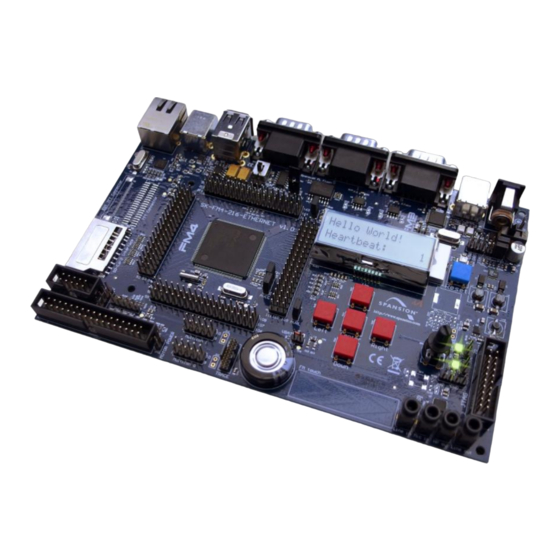
The Hardware (Top Side) – Function Overview Run/Prog CAN1 CAN0 Vin: 9..24V CAN2 (FD) DEBUG Ethernet USB Host switch S1 Device Power MB9AF312K switch S2 Flash Reset 2x16 LCD Module button TFT Interface S6E2CCAL0A SD Card I/F Variable Five user buttons Resistor JTAG Motion Control I/F... - Page 11 Jumper Settings – Power the starterkit ▪ The starter kit can be powered by • External power supply (9-24V) ✓ Set jumpers JP75 and JP77 to position 1-2 Caution: Always set JP75 and JP77 horizontally, never vertically! ✓ Connect X1 to 8..24V DC power ✓...
- Page 12 The Hardware – Connectors SHOW TITLE MM/DD/YY...
- Page 13 Connectors Connectors FM4-216-ETHERNET Number Description Number Description MCU pins 163..216 DCin 9..24V MCU pins 1..54 Debug VCCin (1: before switch, 2: after switch) Ethernet MCU pins 55..108 CAN0 MCU pins 109..162 Audio line out 4x GND Audio headphones out 2x 5V...
- Page 14 Jumper Settings – (Top Side) Regular Solder JP62 JP18 JP56 Jumper Jumper : default position JP75 JP70 JP76 JP71 JP77 JP21 JP28 JP26 JP42 JP40 JP79, 80 JP22 JP44 JP13 JP10 JP73 SHOW TITLE MM/DD/YY...
- Page 15 Jumper Settings – (Bottom Side) Solder JP33 JP23, 24, 27 JP34, 35, 41 JP25 JP49 JP48 JP47 JP72 Jumper JP45, 46, 50-53, 59 JP74 JP57, 58 JP19, 20 JP29-32 JP63-69 JP81 JP78 JP11, 12 JP6, 7 JP43 JP36-39 JP54, 55, 60, 61 JP16, 17 JP14, 15 SHOW TITLE MM/DD/YY...
- Page 16 Jumper Jumper Settings FM4-216-ETHERNET Number Description Special Type Default Number Description Special Type Default USBVCC0 Solder Jumper Closed JP19 MFS0_SOT Solder Jumper Closed USBVCC1 Solder Jumper Closed JP20 MFS0_SIN Solder Jumper Closed ETHVCC Solder Jumper Closed JP21 EthPHY IRQ Solder Jumper Closed...
- Page 17 Jumper Jumper Settings FM4-216-ETHERNET Number Description Special Type Default Number Description Special Type Default JP37 I2SDI Solder Jumper Closed JP55 Touch AN25 Solder Jumper Closed JP38 I2SCK Solder Jumper Closed JP56 CANFDBAT Solder Jumper Closed JP39 I2SWS Solder Jumper Closed...
- Page 18 Jumper Jumper Settings FM4-216-ETHERNET Number Description Special Type Default JP73 I2S48.1k Solder Jumper Closed JP74 USB HCONX Solder Jumper Closed 1-2: External power supply JP75 must JP75 2-3: Supply via USB or JTAG equal 77 1-2: USB Device (X11) Only relevant...
- Page 19 Hardware Pin-List FM4-216-ETHERNET (1/9) Function Description MCUVCC PA0/RTO20_0/TIOA8_0/AIN2_0/INT00_0/MADATA00_0 Pushbutton UP PA1/RTO21_0/TIOA9_0/BIN2_0/MADATA01_0 Pushbutton RIGHT PA2/RTO22_0/TIOA10_0/ZIN2_0/MADATA02_0 Pushbutton CENTER PA3/RTO23_0/TIOA11_0/MADATA03_0 Pushbutton LEFT PA4/RTO24_0/TIOA12_0/MADATA04_0 Pushbutton DOWN PA5/SIN1_0/RTO25_0/TIOA13_0/INT01_0/MADATA05_0 Pushbutton IRQ PA6/SOT1_0/DTTI2X_0/MADATA06_0 PA7/SCK1_0/IC20_0/MADATA07_0 P50/SCS72_0/RTO00_1/TIOA8_2/MADATA16_0 Motor0/MFT0 P51/SCS73_0/RTO01_1/TIOB8_2/MADATA17_0 Motor0/MFT0 P52/RTO02_1/TIOA9_2/MADATA18_0 Motor0/MFT0 P53/RTO03_1/TIOB9_2/MADATA19_0 Motor0/MFT0 PA8/SIN7_0/IC21_0/INT02_0/WKUP1/MADATA08_0 Ethernet PHY IRQ PA9/SOT7_0/IC22_0/MADATA09_0...
- Page 20 Hardware Pin-List FM4-216-ETHERNET (2/9) Function Description PAF/SIN3_0/TIOB11_0/INT16_0/MADATA15_0 P58/SIN11_1/IC01_1/TIOB2_1/INT02_2/MADATA24_0 Motor0/IC0 P59/SOT11_1/IC02_1/TIOB3_1/MADATA25_0 Motor0/IC0 P5A/SCK11_1/IC03_1/TIOB4_1/MADATA26_0 P5B/FRCK0_1/TIOB5_1/MADATA27_0 P08/SIN14_0/TIOB12_0/INT17_0/MDQM0_0 P09/SOT14_0/TIOB13_0/INT18_0/MDQM1_0 P0A/ADTG_1/SCK14_0/AIN2_1/MCLKOUT_0 P5C/TIOA11_2/MADATA28_0/RTCCO_1/SUBOUT_1 Motor0 OPT1 (Brake) P30/RX0_1/TIOA13_2/INT03_2/MDQM2_0/I2SDI_0 I2S serial receive data input pin P31/TX0_1/TIOB13_2/MDQM3_0/I2SCK_0 I2S bit clock terminal P32/BIN2_1/INT19_0/S_DATA1_0 SD I/F P33/FRCK0_0/ZIN2_1/S_DATA0_0 SD I/F P34/IC03_0/INT00_1/S_CLK_0 SD I/F...
- Page 21 Hardware Pin-List FM4-216-ETHERNET (3/9) Function Description P3D/SOT13_0/RTO04_0/TIOA4_1/MAD20_0/MNWEX_0 P3E/SCK13_0/RTO05_0/TIOA5_1/MAD19_0/MNREX_0 P5D/SIN10_1/TIOB11_2/INT01_2/MADATA29_0/I2SMCLK_0 I2S External clock terminal P5E/SOT10_1/TIOA12_2/MADATA30_0/I2SDO_0 I2S serial transmit data output pin P5F/SCK10_1/TIOB12_2/MADATA31_0/I2SWS_0 I2S frame sync signal terminal MCUVCC P40/SIN3_1/RTO10_0/TIOA0_0/AIN0_0/INT23_0/MCSX7_0 TFT Connector (CSYNC) P41/SOT3_1/RTO11_0/TIOA1_0/BIN0_0/MCSX6_0 TFT Connector (DE) P42/SCK3_1/RTO12_0/TIOA2_0/ZIN0_0/MCSX5_0 TFT Connector (DCLK) P43/SIN15_0/RTO13_0/TIOA3_0/INT04_0/MCSX4_0...
- Page 22 Hardware Pin-List FM4-216-ETHERNET (4/9) Function Description P46/X0A [Crystal (Subclock)] P47/X1A [Crystal (Subclock)] VBAT VBAT P48/VREGCTL P49/VWAKEUP PF0/SCS63_0/RX2_1/FRCK1_1/TIOA15_1/INT22_1 PF1/SCS62_0/TX2_1/TIOB15_1/INT23_1 P70/ADTG_8/SIN1_1/INT06_0/MRDY_0/CEC0_0 P71/SOT1_1/MAD00_0 P72/SIN9_0/TIOB0_0/INT07_0/MAD01_0 P73/SOT9_0/TIOB1_0/MAD02_0 P74/SCK9_0/TIOB2_0/MAD03_0 PF2/RTO10_1/TIOA6_1/MRASX_0 PF3/RTO11_1/TIOB6_1/INT05_1/MCASX_0 PF4/RTO12_1/TIOA7_1/INT06_1/MSDWEX_0 PF5/RTO13_1/TIOB7_1/INT07_1/MCSX8_0 Multicon0 Reset PF6/RTO14_1/TIOA14_1/INT20_1/MSDCKE_0 Multicon0 (GINT) PF7/RTO15_1/TIOB14_1/INT21_1/MSDCLK_0 Multicon0 (TINT) P75/SIN8_0/TIOB3_0/AIN1_0/INT20_0/MAD04_0 Multicon0 P76/SOT8_0/TIOB4_0/BIN1_0/MAD05_0 Multicon0 P77/SCK8_0/TIOB5_0/ZIN1_0/MAD06_0...
- Page 23 Hardware Pin-List FM4-216-ETHERNET (5/9) Function Description P79/SOT6_0/IC11_0/MAD08_0 P7A/SCK6_0/IC12_0/MAD09_0 P7B/DA1/SCS60_0/IC13_0/INT22_0 P7C/DA0/SCS61_0/INT04_1 PFA/SCK7_1/IC11_1/ZIN1_1 PFB/SOT7_1/IC12_1/INT07_2 PFC/SIN7_1/IC13_1/INT06_2 PE0/MD1 MD0/ USB Direct Flash PE2/X0 Crystal (mainclock) PE3/X1 Crystal (mainclock) MCUVCC AVCC AVCC AVSS AVSS AVRL AVRL AVRH AVRH P10/AN00/SIN10_0/TIOA0_2/AIN0_2/INT08_0 Motor0/ADC P11/AN01/SOT10_0/TIOB0_2/BIN0_2 Motor0/ADC P12/AN02/SCK10_0/TIOA1_2/ZIN0_2 Motor0/ADC P13/AN03/SIN6_1/RX1_1/INT25_1...
- Page 24 Hardware Pin-List FM4-216-ETHERNET (6/9) Function Description PBA/SOT9_1/BIN2_2/TRACED10 TFT Connector PBB/SCK9_1/ZIN2_2/TRACED11 TFT Connector P15/AN05/SIN11_0/TIOB1_2/AIN1_2/INT09_0 Motor0/ADC P16/AN06/SOT11_0/TIOA2_2/BIN1_2 Motor0/ADC P17/AN07/SCK11_0/TIOB2_2/ZIN1_2 Motor0/ADC PB0/AN16/SCK6_1/TIOA9_1 TFT Connector PB1/AN17/SCS60_1/TIOB9_1/INT08_1 TFT Connector PB2/AN18/SCS61_1/TIOA10_1/INT09_1 TFT Connector PB3/AN19/SCS62_1/TIOB10_1 TFT Connector P18/AN08/SIN2_0/TIOA3_2/INT10_0 Motor0/ADC P19/AN09/SOT2_0/TIOB3_2/INT24_1/TRACECLK TRACE P1A/AN10/SCK2_0/TIOA4_2/TRACED0 TRACE P1B/AN11/SIN12_0/TIOB4_2/INT11_0/TRACED1 TRACE P1C/AN12/SOT12_0/TIOA5_2/TRACED2 TRACE...
- Page 25 Hardware Pin-List FM4-216-ETHERNET (7/9) Function Description P29/AN25/SCK5_0/MAD13_0 Software Touch P28/AN26/SOT5_0/MAD14_0 Software Touch P27/AN27/SIN5_0/INT24_0/MAD15_0 Software Touch PBC/TX1_2/TRACED12 TFT Connector PBD/SCK0_1/RX1_2/AIN3_2/INT10_2/TRACED13 TFT Connector PBE/SOT0_1/BIN3_2/TRACED14 TFT Connector PBF/SIN0_1/ZIN3_2/INT11_2/TRACED15 TFT Connector P26/TX1_0/MAD16_0 CAN1 P25/AN28/RX1_0/INT25_0/MAD17_0 CAN1 P24/AN29/TIOA13_1/MAD18_0 LCD Illumination Dimming P23/UHCONX1/AN30/SCK0_0/TIOB13_1 LCD Reset P22/AN31/SOT0_0/INT26_0 UART/(USB-serial)
- Page 26 Hardware Pin-List FM4-216-ETHERNET (8/9) Function Description P90/INT12_1/Q_IO3_0 QSPI Memory P91/SIN5_1/INT13_1/Q_IO2_0 QSPI Memory P92/SOT5_1/INT14_1/Q_IO1_0 QSPI Memory P93/SCK5_1/INT15_1/Q_IO0_0 QSPI Memory P94/CTS5_1/Q_SCK_0 QSPI Memory P95/RTS5_1/Q_CS0_0 QSPI Memory P96/RX0_2/INT12_2/Q_CS1_0 CAN0 P97/TX0_2/INT13_2/Q_CS2_0 CAN0 PC0/E_RXER Ethernet PC1/TIOB6_0/E_RX03 Ethernet PC2/TIOA6_0/E_RX02 Ethernet PC3/TIOB7_0/E_RX01 Ethernet PC4/TIOA7_0/E_RX00 Ethernet PC5/TIOB14_0/E_RXDV Ethernet...
- Page 27 Hardware Pin-List FM4-216-ETHERNET (9/9) Function Description PCE/SIN4_1/INT15_0/E_TX03 Ethernet PCF/RTS4_1/INT12_0/E_TX02 Ethernet PD0/INT30_1/E_TX01 Ethernet PD1/INT31_1/E_TX00 Ethernet PD2/CTS4_1/FRCK2_1/E_TXEN Ethernet P6E/ADTG_5/SCK4_1/IC23_1/INT29_0/E_PPS Yellow LED on Ethernet connector P6D/SCK14_1/IC22_1/TIOB6_2 HMI SCL P6C/SOT14_1/IC21_1/TIOA6_2 HMI SDA P6B/SIN14_1/IC20_1/TIOB7_2/INT14_2 USB0 Overcurrent IRQ P6A/DTTI2X_1/TIOA7_2 Ethernet PHY Reset P69/RTO20_1/TIOB14_2 Multicon1 Reset P68/SCK13_1/RTO21_1/TIOA14_2...
- Page 28 JP5 is labeled USB PROG but must be UART PROG • The naming labels of RN14 and RN15 near the SD card connector are swapped, there is no electrical problem though • Both errors are rectified on all boards with Cypress branding SHOW TITLE MM/DD/YY...
- Page 29 Software SHOW TITLE MM/DD/YY...
-
Page 30: Software Examples & Tools
✓ ‚Empty‘ project as base for user applications • s6e2cc_ethernet_driver-v16.zip ✓ Cypress low-level Ethernet driver • And several more Note: Please copy the examples to your local drive before compiling! You can find product information of the commercially supported TCP/IP stack by... - Page 31 Software Tools ▪ The following software tools are available • USB Virtual-COM port ✓ allows UART communciation via the PC‘s USB connection ✓ On-board UART-to-USB converter (via X2, CMSIS-DAP) ✓ For driver installation <drive:>\drivers\driverinstaller.exe • FLASH USB DIRECT Programmer ✓ Microcontroller Flash programming (via X12, USB-Device-Port) ✓...
-
Page 32: Flash Programming
Flash Programming SHOW TITLE MM/DD/YY... - Page 33 Flash Programming ▪ There are several options to program the microcontroller’s flash: • FLASH USB DIRECT Programmer via X12 (USB device) ✓ For installation <drive:>\tools\USBDIRECT\setup.exe ✓ USB driver is located in subdirectory of FLASH USB DIRECT Programmer • FLASH MCU Programmer via X2 (Serial via DEBUG USB/Serial bridge) ✓...
- Page 34 Flash Programming via X12 (USB direct) ▪ FLASH USB DIRECT Programming via X12 (USB device) • Jumper Setting ✓ Select the MCU power supply (JP75, 76, 77) ✓ Open JP5 (USB PROG) ✓ Set switch S1 to position PGM • Connect USB port X12 with the PC •...
- Page 35 Flash Programming via X12 (USB device) ▪ Select the correct target MCU: S6E2CCAH0A/J0A/L0A ▪ Browse for the programming file (*.srec or *.hex) • IAR: see subfolder <project>\example\IAR\output\release\exe • ARM/KEIL: see subfolder <project>\example\ARM\output\release ▪ Adjust the corresponding virtual COM-port Select MCU: S6E2CCAH0A/J0A/L0A Select file (*.srec;...
- Page 36 Flash Programming via X2 (Serial) ▪ FLASH MCU Programming via X2 (DEBUG) • Jumper Setting ✓ Select the MCU power supply (JP75, 76, 77) ✓ Close JP5 ✓ Set switch S1 to position PGM • Connect the board via USB CMSIS-DAP (X2) to the USB-Port of the PC ✓...
- Page 37 Flash Programming via X2 (Serial) ▪ Select the correct target MCU: S6E2CCAH0A/J0A/L0A ▪ Select 4MHz Crystal Frequency ▪ Browse for the programming file (*.srec or *.hex) • IAR: see subfolder <project>\example\IAR\output\release\exe • ARM/KEIL: see subfolder <project>\example\ARM\output\release ▪ Adjust the corresponding virtual COM-port Select MCU: S6E2CCAH0A/J0A/L0A Select 4MHz Crystal Frequency Select file (*.srec / *.hex)
- Page 38 JTAG Debugger SHOW TITLE MM/DD/YY...
-
Page 39: Jtag / Cmsis-Dap
JTAG adapter CMSIS-DAP ▪ This starterkit includes an on-board JTAG adapter • Compatible to CMSIS-DAP http://www.keil.com/support/man/docs/dapdebug/dapdebug_introduction.htm • Select debugger CMSIS-DAP in your tool chain ▪ Any other JTAG-adapter can be connected to J14, too. • The correct JTAG-adapter must be selected in the IDE toolchain ✓... - Page 40 JTAG adapter CMSIS-DAP – within IAR EWARM Setup in IAR EWARM (1) Navigate to project options: Via Files-List Right-click at the project Select „Options...“ Or via menu „Project“ Select „Options...“ SHOW TITLE MM/DD/YY...
- Page 41 JTAG adapter CMSIS-DAP – within IAR EWARM Setup in IAR EWARM (2) Setup Project Debbuger Options (1) Navigate to Debugger (2) Select tab „Setup“ (3) Select Driver „CMSIS-DAP“ (4) Select in „CMSIS-DAP“ (5) Select tab „JTAG/SWD“ (6) Select SWD SHOW TITLE MM/DD/YY...
- Page 42 JTAG adapter CMSIS-DAP – within Keil µVision Setup in Keil µVision (1) Navigate to project options: Via Project Right-click at the project Select „Options...“ Or via menu „Project“ Select „Options...“ SHOW TITLE MM/DD/YY...
- Page 43 JTAG adapter CMSIS-DAP – within Keil µVision Setup in Keil µVision (2) Setup Debug & Utilities (1) Select tab „Debug“ (2) Select „CMSIS-DAP Debugger“ (3) Select tab „Utilities“ (4) Select „CMSIS-DAP Debugger“ SHOW TITLE MM/DD/YY...
- Page 44 CMSIS-DAP Firmware update Please see instructions contained in firmware update package! SHOW TITLE MM/DD/YY...
-
Page 45: Iar-Embedded Workbench
IAR Embedded Workbench Installation Getting Started Open Project Build Project Debug Project SHOW TITLE MM/DD/YY... - Page 46 IAR Workbench Getting Started ▪ Install EWARM from IAR-CD or download latest version from IAR Website • EWARM size-limited (32k) or time-limited (full) Evaluation Version ✓ http://supp.iar.com/Download/SW/?item=EWARM-EVAL ▪ Start EWARM Workbench ▪ Choose File → Open → Workspace • e.g.: <drive:>\sw-examples\ SHOW TITLE MM/DD/YY...
- Page 47 IAR Workbench – Main Window ▪ IAR Workbench • Workspace on left side of Workbench window ✓ If hidden then View→Workspace • Source files on right side of Workbench window as tabbed windows • Project open File → Open → Workspace → *.eww •...
- Page 48 IAR Workbench – Menu Bar ▪ IAR Menu Bar File Control Configuration Build Control (new, open, (compile, make, Control save, etc.) stop build) (e.g. RAM or ROM debugging) Navigation Control Debug Control Edit Control (Find, Bookmarks, File (Breakpoint, start (cut, copy, Navigation, etc.) Debug w/ and w/o paste, undo,...
- Page 49 IAR Workbench – Workspace ▪ IAR Workspace Window Project Name Sub Folder Modules Main Modules Module Includes Project Description Project Built Output SHOW TITLE MM/DD/YY...
- Page 50 IAR Workbench – Making Project ▪ Making the Project • Use Make-Icon ( ), <F7> or Menu: Project→Make • Check for no errors in Output window below • Build errors are indicated by In Output window and Source view SHOW TITLE MM/DD/YY...
- Page 51 IAR Workbench – Download to Target ▪ Download to Target and Start Debugging • Icon, <Ctrl>-D, or Project→Download and Debug • A new menu bar will occur on sucessful connection to target Step Run to Reset Step Debugging Cursor Target Over Stop Step...
- Page 52 IAR Workbench – Debug (1) ▪ Source Window • The Source windows do not change contents but get additional information ✓ Current line (PC): ✓ Halted on Breakpoint: ✓ Halted on Data break (example): ▪ Disassembly Window • Shows ‘pure‘ disassebly view •...
- Page 53 IAR Workbench – Debug (2) ▪ Watch Window • Watch ✓ Expressions/Variables have to be added by user and are updated by Halt/Breakpoint • Quick Watch ✓ The Quick watch allows the user to calculate and recalculate expressions even with variables ✓...
- Page 54 IAR Workbench – Simulator ▪ Simulator • Mark Project File in Workspace • Choose Project→Options • Choose Simulator in Debugger Setup • Start Simulator with usual Icon SHOW TITLE MM/DD/YY...
-
Page 55: Keil Μvision
KEIL µVision Installation Getting Started Open Project Build Project Debug Project SHOW TITLE MM/DD/YY... - Page 56 KEIL µVision IDE and Debugger Getting Started ▪ Install µVision from KEIL-CD or download latest version from KEIL Website • Evaluation Version ✓ https://www.keil.com/demo/eval/arm.htm ✓ Registration required ▪ Install ULINK-ME • Special installation is not needed, because ULINK-ME acts as a USB Human Interface Device (HID) and thus needs no extra USB driver ▪...
- Page 57 KEIL µVision – Getting Started ▪ Choose Menu: Project→Open Project... • Browse to: <drive:>\sw-examples\mb9bf56xr_gpio-v10\example\ARM\ • Choose mb9bf56xr_gpio.uvproj SHOW TITLE MM/DD/YY...
- Page 58 KEIL µVision – Main Window ▪ KEIL µVision • Project window on left side of IDE window ✓ Choose: View→Project Window if hidden • Source files on right side of IDE window as tabbed windows • Output window on bottom side of IDE window SHOW TITLE MM/DD/YY...
- Page 59 KEIL µVision – Menu Bars (1) ▪ Menu Bar 1 • Can be moved in bar window area or set floating File Control Navigation Control Project (new, open, (Bookmarks + search, etc.) Window View save, etc.) (Text search, search in files, etc.) Edit Control Debug Control (cut, copy, paste, etc.)
- Page 60 KEIL µVision – Menu Bars (2) ▪ Menu Bar 2 • Can be moved in bar window area or set floating Configuration Build Control Manage Books, Control (Compile [Translate], File Extensions, (e.g. RAM or ROM Build, Rebuild, etc.) Environment debugging) MB9BF51x Release Download Target...
- Page 61 KEIL µVision – Project Window ▪ µVision Project Window Project Name Startup Code Subfolder Startup Code Source and Header Files Main Project Code Subfolder Main Project Code Source and Header Files Project Description Subfolder and Abstract File SHOW TITLE MM/DD/YY...
- Page 62 KEIL µVision – Making Project ▪ Making the Project • Use Rebuild Icon ) or Project→Rebuild all target files • Check for no errors in Output window below • Build errors are shown in Output window. ✓ Can be double-clicked by showing the source line with a blue arrow SHOW TITLE MM/DD/YY...
- Page 63 KEIL µVision – Debug (1) ▪ Start Debugging • Download to target first, when MCU Flash does not contain the current application openend and built in the IDE ✓ Use Download Icon ( ) or Menu: Flash→Download • Start Debug Session ✓...
- Page 64 KEIL µVision – Debug (2) ▪ Debugging Icon Bar • During a Debug Session there will be visible a new icon bar Reset Step Control Show Windows Tool Box (Command, (Step in, out, etc.) Disassembly, Symbols, (can be Target Registers, Call Stack) customized) Debug Start/...
- Page 65 KEIL µVision – Debug (3) ▪ Source View • The Source windows do not change contents but get additional information Active Breakpoint Disabled Breakpoint Current Program Counter Current Cursor Line of Source Code Code Lines with compiled Instructions (dark grey SHOW TITLE MM/DD/YY...
- Page 66 KEIL µVision – Debug (4) ▪ Disassembly View • Mixed mode is selectable and deselectable Active Breakpoint Disabled Breakpoint Current Program Counter Current Cursor Line of Code highlighted in yellow background ( ) SHOW TITLE MM/DD/YY...
- Page 67 KEIL µVision – Debug (5) ▪ Memory Window • Up to 4 Memory windows can be displayed in tabs • Memory is updated during runtime • Memory window tabs are shared with Watch windows ▪ Register View • Register view is a tab of the Project window •...
- Page 68 KEIL µVision – Debug (6) ▪ Variable Windows • Watch Windows ✓ Up to 2 Watch windows are sharing their tabs with e.g. Memory and Local views ✓ Updated during runtime ✓ Any changes are highlighted in dark blue text backround color ✓...
- Page 69 KEIL µVision – Trace (ULINK ME) ▪ Trace via ITM • Simple Trace views via Instrumentation Trace Macro is supported by µLINK ME ✓ Records ✓ Exceptions ✓ Counters SHOW TITLE MM/DD/YY...
- Page 70 KEIL µVision – Trace (ULINK Pro) (1) ▪ Trace via ETM • Check settings in menu: Flash→Configure Flash Tools... Tab:Debug enables ETM pins This small text file must be created first and sets the PFR and EPFR register bits for the TRACE pins.
- Page 71 KEIL µVision – Trace (ULINK Pro) (2) ▪ Instruction Trace • Real Time Trace recording • Output can be filtered by several ETM and ITM events • Trace buffer is held in PC memory and transfered to µVision on break SHOW TITLE MM/DD/YY...
- Page 72 KEIL µVision – Simulator ▪ Simulator • The Core Simulator can be selected by the menu: Flash → Configure Flash Tools... and then choosing Use Simulator • Look & feel is like using ULINK debugger • Controlable also with *.ini files SHOW TITLE MM/DD/YY...
- Page 73 Finally SHOW TITLE MM/DD/YY...
- Page 74 According to the European WEEE-Directive and its implementation into national laws we take this device back. • For disposal please send the device to the following address: Cypress Semiconductor 198 Champion Court San Jose, CA 95134 USA ▪ This board is compliant with China RoHS...
- Page 75 Cypress Support ▪ Please check the following website, for any available updates www.cypress.com Cypress maintains a worldwide network of offices, solution centers, manufacturer’s representatives, and distributors. To find the office closest to you, visit us at Cypress Locations. SHOW TITLE MM/DD/YY...
Need help?
Do you have a question about the FM4-216-ETHERNET and is the answer not in the manual?
Questions and answers