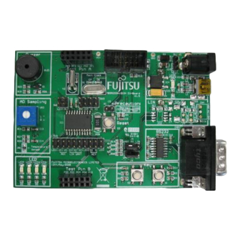
Cypress F2MC-8FX Series How-To
How to make on-board debug
Hide thumbs
Also See for F2MC-8FX Series:
- Setup manual (41 pages) ,
- Operation manual (22 pages) ,
- Application note (16 pages)
Table of Contents
Advertisement
Quick Links
F²MC - 8FX Family, MB95200 Series, How to make on-Board Debug
Debugging on the target board is a very important step in project design. This document will describe how to debug
on a target board. The debugging interface described in this document can be used both as the in-circuit debugging
tool and the in-circuit programming tool.
Contents
1 Introduction .................................................................. 1
2 Application Environment .............................................. 2
2.1 Debug Tool ......................................................... 2
2.2 SOFTUNE ........................................................... 2
3 MCU Products ............................................................. 3
4 Hardware Design ......................................................... 4
4.1 Single Flash MCU Debugging Circuit .................. 4
4.2 Dual Flash MCU Debugging Circuit .................... 5
1
Introduction
Debugging on the target board is a very important step in project design. This document will describe how to debug
on a target board.
The debugging interface described in this document can be used both as the in-circuit debugging tool and the in-
circuit programming tool.
www.cypress.com
5 Debugging Operation .................................................. 7
6 Additional Information ................................................ 12
Document History ............................................................ 13
Document No. 002-05390 Rev. *A
SOFTUNE ........................................................... 7
2
MC-8L/8FX SOFTUNE .......... 8
AN205390
2
1
Advertisement
Table of Contents

Summary of Contents for Cypress F2MC-8FX Series
-
Page 1: Table Of Contents
Debugging on the target board is a very important step in project design. This document will describe how to debug on a target board. The debugging interface described in this document can be used both as the in-circuit debugging tool and the in- circuit programming tool. www.cypress.com Document No. 002-05390 Rev. *A... -
Page 2: Application Environment
SOFTUNE is used as software development environment for programming and debugging. The version currently being used is F MC-8L/8FX SOFTUNE Workbench V30L31, as shown below in the picture. It is available in the MB95200 MCU Starter Kit (PN: MB2146-410-01-E) Figure 2. SOFTUNE Version www.cypress.com Document No. 002-05390 Rev.*A... -
Page 3: Mcu Products
MB95F213H MB95F273H MB95F210H Flash MB95F270H Flash MB95F214K MB95F274K MB95F214H MB95F274H MB95F222K MB95F282K MB95F222H MB95F282H MB95F223K MB95F283K Single Dual MB95F223H MB95F283H MB95F220H Flash MB95F280H Flash MB95F284K MB95F284H MB95F332K MB95F332H MB95F333K MB95F333H Dual MB95F334K Flash MB95F334H MB95F330H www.cypress.com Document No. 002-05390 Rev.*A... -
Page 4: Hardware Design
The DBG pin provides 1-line UART communication with the debugger. Serial write mode can be set by providing special timing of DBG and VCC pins. If the MCU target needs a reset circuit, please design the reset circuit according to the diagram below. www.cypress.com Document No. 002-05390 Rev.*A... -
Page 5: Dual Flash Mcu Debugging Circuit
The DBG pin provides 1-line UART communication with the debugger. Serial write mode can be set by providing special timing of DBG and VCC pins. If the MCU target need a reset circuit, and please design a reset circuit as follow circuit. www.cypress.com Document No. 002-05390 Rev.*A... - Page 6 Pin 4 of the connector is used to connect to the reset circuit. Design a switch K1 between the reset circuit and the reset pin (RSTX). When debugging operation is over, K1 can be switched on to supply the reset circuit to the target MCU. www.cypress.com Document No. 002-05390 Rev.*A...
-
Page 7: Debugging Operation
(Note that user can only power on the MCU after connecting the target board to the BGM adaptor). Power on the EV-board. Figure 7. Step 1-3 Open a project (E.g. IO_LED) using SOFTUNE. Figure 8. Open the Demo Project www.cypress.com Document No. 002-05390 Rev.*A... -
Page 8: Debugging With Fmc-8L/8Fx Softune
Start debugging. (by clicking Start Debug in Debug) Figure 9. Start Debugging Start Debugging (Code Update) Select Debug -> Run to start debugging or use the shortcut key as indicated in Figure Figure 10. Run Operation www.cypress.com Document No. 002-05390 Rev.*A... - Page 9 Figure 12. Register Operation Memory Operation Then select View -> Memory to display the Memory window, Address content can be modified by highlight the address and then type the new value. Figure 13. Memory Operation www.cypress.com Document No. 002-05390 Rev.*A...
- Page 10 Highlight the symbol to be watched. Right click and select Watch in the shortcut menu. Figure 14. Select the Watch Window Put the mouse pointer inside the window. Right click and select Monitoring from shortcut menu to monitor symbols continuously. Figure 15. Continuously Monitoring www.cypress.com Document No. 002-05390 Rev.*A...
- Page 11 Set breakpoints by clicking the green circle in the code, as shown in the figure below. Figure 16. Breakpoints Setting Method 1 Another way to set breakpoints is specifying the program address or data address by selecting Debug -> Breakpoints. Figure 17. Breakpoints Setting Method 2 www.cypress.com Document No. 002-05390 Rev.*A...
-
Page 12: Additional Information
F²MC - 8FX Family, MB95200 Series, How to make on-Board Debug Additional Information For more information on Cypress Microcontrollers Products, please visit the following websites: http://www.cypress.com/cypress-microcontrollers http://www.cypress.com/cypress-mcu-product-softwareexamples www.cypress.com Document No. 002-05390 Rev.*A... -
Page 13: Document History
Document Title: AN205390 – F²MC - 8FX Family, MB95200 Series, How to make on-Board Debug Document Number: 002-05390 Orig. of Submission Revision Description of Change Change Date Benjamin. 02/09/2009 V1.0, First Draft Yang 02/13/2009 Modify 5267684 HUAL 05/11/2016 Migrated Spansion Application Note “MCU-AN-500018-E-11” to Cypress format. www.cypress.com Document No. 002-05390 Rev.*A... - Page 14 Cypress is not liable, in whole or in part, and you shall and hereby do release Cypress from any claim, damage, or other liability arising from or related to all Unintended Uses of Cypress products.


Need help?
Do you have a question about the F2MC-8FX Series and is the answer not in the manual?
Questions and answers