Table of Contents
Advertisement
Quick Links
Please note that Cypress is an Infineon Technologies Company.
The document following this cover page is marked as "Cypress" document as this is the
company that originally developed the product. Please note that Infineon will continue
to offer the product to new and existing customers as part of the Infineon product
portfolio.
Continuity of document content
The fact that Infineon offers the following product as part of the Infineon product
portfolio does not lead to any changes to this document. Future revisions will occur
when appropriate, and any changes will be set out on the document history page.
Continuity of ordering part numbers
Infineon continues to support existing part numbers. Please continue to use the
ordering part numbers listed in the datasheet for ordering.
www.infineon.com
Advertisement
Table of Contents

Subscribe to Our Youtube Channel
Related Manuals for Cypress CYTVII-B-H-8M-176-CPU


Summary of Contents for Cypress CYTVII-B-H-8M-176-CPU
- Page 1 Please note that Cypress is an Infineon Technologies Company. The document following this cover page is marked as “Cypress” document as this is the company that originally developed the product. Please note that Infineon will continue to offer the product to new and existing customers as part of the Infineon product portfolio.
- Page 2 CYTVII-B-H-8M-176-CPU Evaluation board user guide Document Number: 002-25907 Rev. *D Cypress Semiconductor An Infineon Technologies Company 198 Champion Court San Jose, CA 95134-1709 www.cypress.com, www.infineon.com...
- Page 3 High-Risk Device, or to affect its safety or effectiveness. Cypress is not liable, in whole or in part, and you shall and hereby do release Cypress from any claim, damage, or other liability arising from any use of a Cypress product as a Critical Component in a High-Risk Device.
-
Page 4: Table Of Contents
Settings........................25 5. Power management IC (PMIC) Power management IC (PMIC) module ..............26 A. CPU board schematics B. CPU board component assembly C. Baseboard schematics D. Baseboard component assembly Revision history CYTVII-B-H-8M-176-CPU Evaluation Board User Guide, Document Number: 002-25907 Rev. *D... -
Page 5: Introduction
Introduction This user guide provides instructions to handle the CYTVII-B-H-8M-176-CPU and CYTVII-B-H-176-SO evaluation boards, collectively referred to as ‘CPU board’ in this document. This is an evaluation platform for the CYT4BF8C TRAVEO™ T2G device. The board can be used as a standalone for basic validation or in combination with the CYTVII-B-E-BB TRAVEO™... -
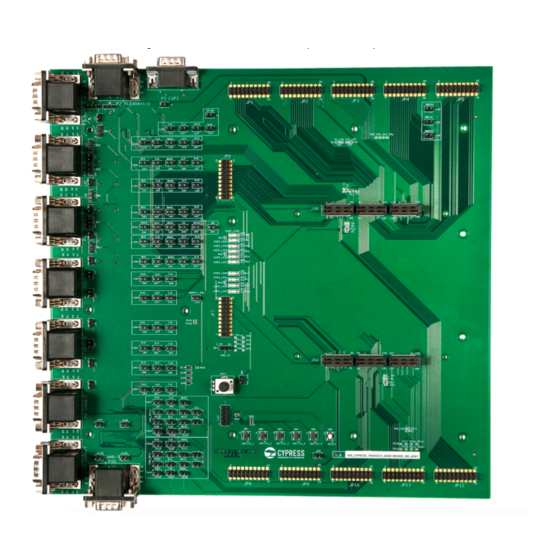
Page 6: Overview
Overview Figure 2-1 shows the CYTVII-B-H-176-SO board. Insert a TRAVEO™ T2G device into the IC socket (highlighted in red) while the evaluation board is powered OFF. Figure 2-1. CYTVII-B-H-176-SO board CYTVII-B-H-8M-176-CPU Evaluation Board User Guide, Document Number: 002-25907 Rev. *D... - Page 7 Overview A variant of the CPU board (CYTVII-B-H-8M-176-CPU) is also available, where the TRAVEO™ T2G device is soldered directly onto the PCB. Functionally, the CYTVII-B-H-8M-176-CPU and CYTVII-B-H-176-SO boards are identical, except that the device can be easily replaced in the latter.
-
Page 8: Functional Overview
4. USB-UART interface for terminal logging (J25) 5. Two user switches (SW2 and SW4) and two user LEDs (LED4 and LED5) for standalone operation without the baseboard 6. One hibernate wakeup switch. (SW3) CYTVII-B-H-8M-176-CPU Evaluation Board User Guide, Document Number: 002-25907 Rev. *D... - Page 9 8. Pin headers to access all I/Os of the TRAVEO™ T2G device (when a CPU board is connected to the baseboard) 9. Samtec connector interface (J38 and J84) for connecting to a CPU board CYTVII-B-H-8M-176-CPU Evaluation Board User Guide, Document Number: 002-25907 Rev. *D...
- Page 10 (PMIC) eMMC Dual Quad Connector SPI Flash Pass Transistor SMIF HyperFlash HyperRAM Traveo II Connector CYT4BF Series 176-Pin MCU Debug Reset Interfaces Controller USB-UART S Audio Interface 3.5mm Audio Jack CYTVII-B-H-8M-176-CPU Evaluation Board User Guide, Document Number: 002-25907 Rev. *D...
- Page 11 Overview 2.1.2 USB connector Figure 2-5. USB connector CYTVII-B-H-8M-176-CPU Evaluation Board User Guide, Document Number: 002-25907 Rev. *D...
- Page 12 Overview 2.1.3 Ethernet connector Figure 2-6. Ethernet connector CYTVII-B-H-8M-176-CPU Evaluation Board User Guide, Document Number: 002-25907 Rev. *D...
- Page 13 Overview 2.1.4 SMIF connector Figure 2-7. SMIF connector CYTVII-B-H-8M-176-CPU Evaluation Board User Guide, Document Number: 002-25907 Rev. *D...
- Page 14 Overview 2.1.5 eMMC connector Figure 2-8. eMMC connector CYTVII-B-H-8M-176-CPU Evaluation Board User Guide, Document Number: 002-25907 Rev. *D...
- Page 15 Overview 2.1.6 Audio connector Figure 2-9. Audio Connector CYTVII-B-H-8M-176-CPU Evaluation Board User Guide, Document Number: 002-25907 Rev. *D...
-
Page 16: Operation
7. Connect an appropriate programming tool to one of the programming interfaces (J19, J20, J21, J22). Programming tool options are: ETM MICTOR on J19 ® Cortex ® DEBUG on J20 ® Standard JTAG on J21 Cortex DEBUG and ETM on J22 ® CYTVII-B-H-8M-176-CPU Evaluation Board User Guide, Document Number: 002-25907 Rev. *D... - Page 17 8. Install the appropriate programming integrated design environment (IDE) on a PC. The programming IDE (GHS MULTI, IAR Embedded Workbench, Cypress Programmer, and so on) should be able to detect a device (read the device ID) and to load a firmware HEX file (.srec) into the device flash successfully.
-
Page 18: Connections And Settings
Apart from these interface transceivers that can be used for specific functions, all pins of the device are also accessible on the baseboard using pin headers JP1 through JP12. The device port pins are connected to pin headers on the baseboard as listed in Table 4-1. CYTVII-B-H-8M-176-CPU Evaluation Board User Guide, Document Number: 002-25907 Rev. *D... - Page 19 R197.1, R247.1 Not applicable P6.4 GPIO_P6_4 R196.1, R221.1 Not applicable P6.5 GPIO_P6_5 R198.1, R223.1 Not applicable P6.6 GPIO_P6_6 Not applicable JP10.10 P6.7 GPIO_P6_7 Not applicable JP10.9 VDDD Not applicable Not applicable CYTVII-B-H-8M-176-CPU Evaluation Board User Guide, Document Number: 002-25907 Rev. *D...
- Page 20 P12.3 GPIO_P12_3 Not applicable JP10.13 P12.4 BB_CAN4_TXD Not applicable JP11.8 P12.5 BB_CAN4_RXD Not applicable JP11.7 P12.6 BB_ADC_POT Not applicable JP7.11 P12.7 GPIO_P12_7 TP184 JP11.4 VDDIO_2 Not applicable TP11 Not applicable CYTVII-B-H-8M-176-CPU Evaluation Board User Guide, Document Number: 002-25907 Rev. *D...
- Page 21 R229.1, R230.1 Not applicable P18.5 GPIO_P18_5 R231.1, R232.1 Not applicable P18.6 GPIO_P18_6 R233.1, R234.1 Not applicable P18.7 GPIO_P18_7 R235.1, R236.1 Not applicable VDDD Not applicable Not applicable VSSD Not applicable CYTVII-B-H-8M-176-CPU Evaluation Board User Guide, Document Number: 002-25907 Rev. *D...
- Page 22 Not applicable P23.7 SWDOE_TDI_PRM J38.1 Not applicable VDDD Not applicable Not applicable The first column in Table 4-1 lists the pin number on the MCU, followed by the port pin name. CYTVII-B-H-8M-176-CPU Evaluation Board User Guide, Document Number: 002-25907 Rev. *D...
- Page 23 The correspondence between the User LEDs and port number is given in Table 4-5. Table 4-5. User LEDs Switch Part No. Port Name User LED1 LED4 P3.2 User LED2 LED5 P3.3 CYTVII-B-H-8M-176-CPU Evaluation Board User Guide, Document Number: 002-25907 Rev. *D...
-
Page 24: Power Supply Settings
VDDIO_1 = +5.0 V 1-2 (default) VDDIO_2 = +3.3 V Short Jumper - J9 VDDIO_2 = +5.0 V 1-2 (default) VDDA = +3.3 V Short Jumper - J11 VDDA = +5.0 V CYTVII-B-H-8M-176-CPU Evaluation Board User Guide, Document Number: 002-25907 Rev. *D... -
Page 25: External Power Supply Control Signal Settings
EXT_PS_CTL1 J42 close (default) Ethernet settings Ethernet settings are shown in Table 4-9. Table 4-9. Ethernet settings Function status Jumper Settings Remarks Ethernet is enabled Closed Ethernet is disabled Open CYTVII-B-H-8M-176-CPU Evaluation Board User Guide, Document Number: 002-25907 Rev. *D... -
Page 26: Settings
Connections and settings Settings Settings are shown in Table 4-10. Table 4-10. Settings Function status Jumper Settings Remarks is enabled Closed is disabled Open CYTVII-B-H-8M-176-CPU Evaluation Board User Guide, Document Number: 002-25907 Rev. *D... -
Page 27: Power Management Ic (Pmic)
SMPS Boost PGND VOUT1V 1.10V / 0.02A – 0.75A FB1V_IN SMPS Buck to FB1V_IN PGND EN5V Logic / EN1V PG5V EN3V PG3V Power SYNC PG1V *SMPS: Switching Mode Power Supply CYTVII-B-H-8M-176-CPU Evaluation Board User Guide, Document Number: 002-25907 Rev. *D... - Page 28 1.1 V power rail output enable terminal N.C. N.C. No connection 23, 24 PGND – Ground terminal 25, 26 DC power supply terminal (4.5 V-42 V, 12 V typ.) Figure 5-2. Pin layout CYTVII-B-H-8M-176-CPU Evaluation Board User Guide, Document Number: 002-25907 Rev. *D...
-
Page 29: Cpu Board Schematics
CPU board schematics CYTVII-B-H-8M-176-CPU Evaluation Board User Guide, Document Number: 002-25907 Rev. *D... - Page 30 R e v VJYM VJYM VJYM SPPD SPPD SPPD 60555 60555 60555 Date: Date: Date: Thursday, September 02, 2021 Thursday, September 02, 2021 Thursday, September 02, 2021 Sheet Sheet Sheet CYTVII-B-H-8M-176-CPU Evaluation Board User Guide, Document Number: 002-25907 Rev. *D...
- Page 31 R e v VJYM VJYM VJYM SPPD SPPD SPPD 60555 60555 60555 Date: Date: Date: Thursday, September 02, 2021 Thursday, September 02, 2021 Thursday, September 02, 2021 Sheet Sheet Sheet CYTVII-B-H-8M-176-CPU Evaluation Board User Guide, Document Number: 002-25907 Rev. *D...
- Page 32 R e v 60555 60555 60555 VJYM VJYM VJYM SPPD SPPD SPPD Date: Date: Date: Thursday, September 02, 2021 Thursday, September 02, 2021 Thursday, September 02, 2021 Sheet Sheet Sheet CYTVII-B-H-8M-176-CPU Evaluation Board User Guide, Document Number: 002-25907 Rev. *D...
- Page 33 R e v 60555 60555 60555 VJYM VJYM VJYM SPPD SPPD SPPD Date: Date: Date: Thursday, September 02, 2021 Thursday, September 02, 2021 Thursday, September 02, 2021 Sheet Sheet Sheet CYTVII-B-H-8M-176-CPU Evaluation Board User Guide, Document Number: 002-25907 Rev. *D...
- Page 34 R e v 60555 60555 60555 VJYM VJYM VJYM SPPD SPPD SPPD Date: Date: Date: Thursday, September 02, 2021 Thursday, September 02, 2021 Thursday, September 02, 2021 Sheet Sheet Sheet CYTVII-B-H-8M-176-CPU Evaluation Board User Guide, Document Number: 002-25907 Rev. *D...
- Page 35 R e v VJYM VJYM VJYM SPPD SPPD SPPD 60555 60555 60555 Date: Date: Date: Thursday, September 02, 2021 Thursday, September 02, 2021 Thursday, September 02, 2021 Sheet Sheet Sheet CYTVII-B-H-8M-176-CPU Evaluation Board User Guide, Document Number: 002-25907 Rev. *D...
- Page 36 R e v 60555 60555 60555 VJYM VJYM VJYM SPPD SPPD SPPD Date: Date: Date: Thursday, September 02, 2021 Thursday, September 02, 2021 Thursday, September 02, 2021 Sheet Sheet Sheet CYTVII-B-H-8M-176-CPU Evaluation Board User Guide, Document Number: 002-25907 Rev. *D...
- Page 37 R e v 60555 60555 60555 VJYM VJYM VJYM SPPD SPPD SPPD Date: Date: Date: Thursday, September 02, 2021 Thursday, September 02, 2021 Thursday, September 02, 2021 Sheet Sheet Sheet CYTVII-B-H-8M-176-CPU Evaluation Board User Guide, Document Number: 002-25907 Rev. *D...
- Page 38 R e v 60555 60555 60555 VJYM VJYM VJYM SPPD SPPD SPPD Date: Date: Date: Thursday, September 02, 2021 Thursday, September 02, 2021 Thursday, September 02, 2021 Sheet Sheet Sheet CYTVII-B-H-8M-176-CPU Evaluation Board User Guide, Document Number: 002-25907 Rev. *D...
- Page 39 R e v 60555 60555 60555 VJYM VJYM VJYM SPPD SPPD SPPD Date: Date: Date: Thursday, September 02, 2021 Thursday, September 02, 2021 Thursday, September 02, 2021 Sheet Sheet Sheet CYTVII-B-H-8M-176-CPU Evaluation Board User Guide, Document Number: 002-25907 Rev. *D...
- Page 40 R e v 60555 60555 60555 VJYM VJYM VJYM SPPD SPPD SPPD Date: Date: Date: Thursday, September 02, 2021 Thursday, September 02, 2021 Thursday, September 02, 2021 Sheet Sheet Sheet CYTVII-B-H-8M-176-CPU Evaluation Board User Guide, Document Number: 002-25907 Rev. *D...
- Page 41 R e v 60555 60555 60555 VJYM VJYM VJYM SPPD SPPD SPPD Date: Date: Date: Thursday, September 02, 2021 Thursday, September 02, 2021 Thursday, September 02, 2021 Sheet Sheet Sheet CYTVII-B-H-8M-176-CPU Evaluation Board User Guide, Document Number: 002-25907 Rev. *D...
- Page 42 R e v 60555 60555 60555 VJYM VJYM VJYM SPPD SPPD SPPD Date: Date: Date: Thursday, September 02, 2021 Thursday, September 02, 2021 Thursday, September 02, 2021 Sheet Sheet Sheet CYTVII-B-H-8M-176-CPU Evaluation Board User Guide, Document Number: 002-25907 Rev. *D...
- Page 43 R e v 60555 60555 60555 VJYM VJYM VJYM SPPD SPPD SPPD Date: Date: Date: Thursday, September 02, 2021 Thursday, September 02, 2021 Thursday, September 02, 2021 Sheet Sheet Sheet CYTVII-B-H-8M-176-CPU Evaluation Board User Guide, Document Number: 002-25907 Rev. *D...
- Page 44 R e v 60555 60555 60555 VJYM VJYM VJYM SPPD SPPD SPPD Date: Date: Date: Thursday, September 02, 2021 Thursday, September 02, 2021 Thursday, September 02, 2021 Sheet Sheet Sheet CYTVII-B-H-8M-176-CPU Evaluation Board User Guide, Document Number: 002-25907 Rev. *D...
- Page 45 R e v 60555 60555 60555 VJYM VJYM VJYM SPPD SPPD SPPD Date: Date: Date: Thursday, September 02, 2021 Thursday, September 02, 2021 Thursday, September 02, 2021 Sheet Sheet Sheet CYTVII-B-H-8M-176-CPU Evaluation Board User Guide, Document Number: 002-25907 Rev. *D...
- Page 46 R e v 60555 60555 60555 VJYM VJYM VJYM SPPD SPPD SPPD Date: Date: Date: Thursday, September 02, 2021 Thursday, September 02, 2021 Thursday, September 02, 2021 Sheet Sheet Sheet CYTVII-B-H-8M-176-CPU Evaluation Board User Guide, Document Number: 002-25907 Rev. *D...
- Page 47 R e v 60555 60555 60555 VJYM VJYM VJYM SPPD SPPD SPPD Date: Date: Date: Thursday, September 02, 2021 Thursday, September 02, 2021 Thursday, September 02, 2021 Sheet Sheet Sheet CYTVII-B-H-8M-176-CPU Evaluation Board User Guide, Document Number: 002-25907 Rev. *D...
- Page 48 R e v 60555 60555 60555 VJYM VJYM VJYM SPPD SPPD SPPD Date: Date: Date: Thursday, September 02, 2021 Thursday, September 02, 2021 Thursday, September 02, 2021 Sheet Sheet Sheet CYTVII-B-H-8M-176-CPU Evaluation Board User Guide, Document Number: 002-25907 Rev. *D...
- Page 49 R e v 60555 60555 60555 VJYM VJYM VJYM SPPD SPPD SPPD Date: Date: Date: Thursday, September 02, 2021 Thursday, September 02, 2021 Thursday, September 02, 2021 Sheet Sheet Sheet CYTVII-B-H-8M-176-CPU Evaluation Board User Guide, Document Number: 002-25907 Rev. *D...
- Page 50 R e v 60555 60555 60555 VJYM VJYM VJYM SPPD SPPD SPPD Date: Date: Date: Thursday, September 02, 2021 Thursday, September 02, 2021 Thursday, September 02, 2021 Sheet Sheet Sheet CYTVII-B-H-8M-176-CPU Evaluation Board User Guide, Document Number: 002-25907 Rev. *D...
- Page 51 R e v 60555 60555 60555 VJYM VJYM VJYM SPPD SPPD SPPD Date: Date: Date: Thursday, September 02, 2021 Thursday, September 02, 2021 Thursday, September 02, 2021 Sheet Sheet Sheet CYTVII-B-H-8M-176-CPU Evaluation Board User Guide, Document Number: 002-25907 Rev. *D...
- Page 52 R e v 60555 60555 60555 VJYM VJYM VJYM SPPD SPPD SPPD Date: Date: Date: Thursday, September 02, 2021 Thursday, September 02, 2021 Thursday, September 02, 2021 Sheet Sheet Sheet CYTVII-B-H-8M-176-CPU Evaluation Board User Guide, Document Number: 002-25907 Rev. *D...
- Page 53 R e v 60555 60555 60555 VJYM VJYM VJYM SPPD SPPD SPPD Date: Date: Date: Thursday, September 02, 2021 Thursday, September 02, 2021 Thursday, September 02, 2021 Sheet Sheet Sheet CYTVII-B-H-8M-176-CPU Evaluation Board User Guide, Document Number: 002-25907 Rev. *D...
- Page 54 MEM_RSTX {27} {10,16,17,18,22,24} CPU_XRES 60555 60555 60555 VJYM VJYM VJYM SPPD SPPD SPPD Date: Date: Date: Thursday, September 02, 2021 Thursday, September 02, 2021 Thursday, September 02, 2021 Sheet Sheet Sheet CYTVII-B-H-8M-176-CPU Evaluation Board User Guide, Document Number: 002-25907 Rev. *D...
- Page 55 R e v 60555 60555 60555 VJYM VJYM VJYM SPPD SPPD SPPD Date: Date: Date: Thursday, September 02, 2021 Thursday, September 02, 2021 Thursday, September 02, 2021 Sheet Sheet Sheet CYTVII-B-H-8M-176-CPU Evaluation Board User Guide, Document Number: 002-25907 Rev. *D...
- Page 56 R e v 60555 60555 60555 VJYM VJYM VJYM SPPD SPPD SPPD Date: Date: Date: Thursday, September 02, 2021 Thursday, September 02, 2021 Thursday, September 02, 2021 Sheet Sheet Sheet CYTVII-B-H-8M-176-CPU Evaluation Board User Guide, Document Number: 002-25907 Rev. *D...
- Page 57 R e v 60555 60555 60555 VJYM VJYM VJYM SPPD SPPD SPPD Date: Date: Date: Thursday, September 02, 2021 Thursday, September 02, 2021 Thursday, September 02, 2021 Sheet Sheet Sheet CYTVII-B-H-8M-176-CPU Evaluation Board User Guide, Document Number: 002-25907 Rev. *D...
- Page 58 R e v 60555 60555 60555 VJYM VJYM VJYM SPPD SPPD SPPD Date: Date: Date: Thursday, September 02, 2021 Thursday, September 02, 2021 Thursday, September 02, 2021 Sheet Sheet Sheet CYTVII-B-H-8M-176-CPU Evaluation Board User Guide, Document Number: 002-25907 Rev. *D...
- Page 59 R e v 60555 60555 60555 VJYM VJYM VJYM SPPD SPPD SPPD Date: Date: Date: Thursday, September 02, 2021 Thursday, September 02, 2021 Thursday, September 02, 2021 Sheet Sheet Sheet CYTVII-B-H-8M-176-CPU Evaluation Board User Guide, Document Number: 002-25907 Rev. *D...
- Page 60 R e v 60555 60555 60555 VJYM VJYM VJYM SPPD SPPD SPPD Date: Date: Date: Thursday, September 02, 2021 Thursday, September 02, 2021 Thursday, September 02, 2021 Sheet Sheet Sheet CYTVII-B-H-8M-176-CPU Evaluation Board User Guide, Document Number: 002-25907 Rev. *D...
-
Page 61: Cpu Board Component Assembly
CPU board component assembly CYTVII-B-H-8M-176-CPU Evaluation Board User Guide, Document Number: 002-25907 Rev. *D... - Page 62 Figure B-1. Component assembly (top) CYTVII-B-H-8M-176-CPU Evaluation Board User Guide, Document Number: 002-25907 Rev. *D...
- Page 63 Figure B-2. Component assembly (bottom) CYTVII-B-H-8M-176-CPU Evaluation Board User Guide, Document Number: 002-25907 Rev. *D...
-
Page 64: Baseboard Schematics
Baseboard schematics CYTVII-B-H-8M-176-CPU Evaluation Board User Guide, Document Number: 002-25907 Rev. *D... - Page 65 Figure C-1. Schematic (1/16) CYTVII-B-H-8M-176-CPU Evaluation Board User Guide, Document Number: 002-25907 Rev. *D...
- Page 66 Figure C-2. Schematic (2/16) CYTVII-B-H-8M-176-CPU Evaluation Board User Guide, Document Number: 002-25907 Rev. *D...
- Page 67 Figure C-3. Schematic (3/16) CYTVII-B-H-8M-176-CPU Evaluation Board User Guide, Document Number: 002-25907 Rev. *D...
- Page 68 Figure C-4. Schematic (4/16) CYTVII-B-H-8M-176-CPU Evaluation Board User Guide, Document Number: 002-25907 Rev. *D...
- Page 69 Figure C-5. Schematic (5/16) CYTVII-B-H-8M-176-CPU Evaluation Board User Guide, Document Number: 002-25907 Rev. *D...
- Page 70 Figure C-6. Schematic (6/16) CYTVII-B-H-8M-176-CPU Evaluation Board User Guide, Document Number: 002-25907 Rev. *D...
- Page 71 Figure C-7. Schematic (7/16) CYTVII-B-H-8M-176-CPU Evaluation Board User Guide, Document Number: 002-25907 Rev. *D...
- Page 72 Figure C-8. Schematic (8/16) CYTVII-B-H-8M-176-CPU Evaluation Board User Guide, Document Number: 002-25907 Rev. *D...
- Page 73 Figure C-9. Schematic (9/16) CYTVII-B-H-8M-176-CPU Evaluation Board User Guide, Document Number: 002-25907 Rev. *D...
- Page 74 Figure C-10. Schematic (10/16) CYTVII-B-H-8M-176-CPU Evaluation Board User Guide, Document Number: 002-25907 Rev. *D...
- Page 75 Figure C-11. Schematic (11/16) CYTVII-B-H-8M-176-CPU Evaluation Board User Guide, Document Number: 002-25907 Rev. *D...
- Page 76 Figure C-12. Schematic (12/16) CYTVII-B-H-8M-176-CPU Evaluation Board User Guide, Document Number: 002-25907 Rev. *D...
- Page 77 Figure C-13. Schematic (13/16) CYTVII-B-H-8M-176-CPU Evaluation Board User Guide, Document Number: 002-25907 Rev. *D...
- Page 78 Figure C-14. Schematic (14/16) CYTVII-B-H-8M-176-CPU Evaluation Board User Guide, Document Number: 002-25907 Rev. *D...
- Page 79 Figure C-15. Schematic (15/16) CYTVII-B-H-8M-176-CPU Evaluation Board User Guide, Document Number: 002-25907 Rev. *D...
- Page 80 Figure C-16. Schematic (16/16) CYTVII-B-H-8M-176-CPU Evaluation Board User Guide, Document Number: 002-25907 Rev. *D...
-
Page 81: Baseboard Component Assembly
Baseboard component assembly CYTVII-B-H-8M-176-CPU Evaluation Board User Guide, Document Number: 002-25907 Rev. *D... - Page 82 Figure D-1. Component assembly (top) CYTVII-B-H-8M-176-CPU Evaluation Board User Guide, Document Number: 002-25907 Rev. *D...
- Page 83 Figure D-2. Component assembly (bottom) CYTVII-B-H-8M-176-CPU Evaluation Board User Guide, Document Number: 002-25907 Rev. *D...
-
Page 84: Revision History
Updated Figure 2-7. Updated “eMMC connector” on page Updated Figure 2-8. Updated “Audio connector” on page Updated Figure 2-9. Updated CPU board schematics chapter on page Updated all existing schematics. CYTVII-B-H-8M-176-CPU Evaluation Board User Guide, Document Number: 002-25907 Rev. *D...
Need help?
Do you have a question about the CYTVII-B-H-8M-176-CPU and is the answer not in the manual?
Questions and answers