
Related Manuals for Cypress CY8CKIT-148


Summary of Contents for Cypress CY8CKIT-148
- Page 1 CY8CKIT-148 ® PSoC 4700S Inductive Sensing Evaluation Kit Guide Doc. #: 002-23165 Rev. *B Cypress Semiconductor 198 Champion Court San Jose, CA 95134-1709 www.cypress.com...
- Page 2 Cypress is not liable, in whole or in part, and you shall and hereby do release Cypress from any claim, damage, or other liability arising from or related to all Unintended Uses of Cypress products.
-
Page 3: Table Of Contents
USB-UART Bridge .....................26 USB-I2C Bridge ......................27 Updating the KitProg2 Firmware................27 4. Code Examples Using the Kit Code Examples ..................28 Using Built-in PSoC Creator Code Examples with the Kit .........32 CY8CKIT-148 PSoC® 4700S Inductive Sensing Evaluation Kit Guide, Doc. #: 002-23165 Rev. *B... - Page 4 A.2.3 Power Supply System ...................38 A.2.4 Header Connections ..................39 A.2.5 User and Passive Inputs ................40 PSoC 4700S Inductive Sensing Evaluation Kit Schematics ........49 Bill of Materials ......................49 Revision History CY8CKIT-148 PSoC® 4700S Inductive Sensing Evaluation Kit Guide, Doc. #: 002-23165 Rev. *B...
-
Page 5: Safety Information
Safety Information Regulatory Compliance The CY8CKIT-148 PSoC 4700S Inductive Sensing Evaluation Kit is intended for use as a evaluation platform for hardware or software in a laboratory environment. The board is an open system design, which does not include a shielded enclosure. This may cause interference to other electrical or electronic devices in close proximity. - Page 6 Handling Boards The CY8CKIT-148 PSoC 4700S Inductive Sensing Evaluation Kit board is sensitive to ESD. Hold the board only by its edges. After removing the board from its box, place it on a grounded, static-free surface.
-
Page 7: Introduction
■ The CY8CKIT-148 PSoC 4700S Inductive Sensing Evaluation Kit also integrates a Cypress KitProg2 that enables onboard programming, debugging, and bridging functionalities, such as USB-UART and USB-I2C. CY8CKIT-148 PSoC® 4700S Inductive Sensing Evaluation Kit Guide, Doc. #: 002-23165 Rev. *B... -
Page 8: Kit Contents
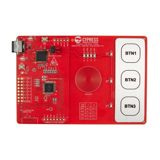
The PSoC 4700S Inductive Sensing Evaluation Kit contains a PSoC 4700S Evaluation board, Metal Target, USB Type-A to Type-C Cable and Quick Start Guide. Figure 1-1. CY8CKIT-148 PSoC 4700S Inductive Sensing Evaluation Kit Figure 1-2. Metal Target CY8CKIT-148 PSoC® 4700S Inductive Sensing Evaluation Kit Guide, Doc. #: 002-23165 Rev. *B... -
Page 9: Psoc Creator
PSoC Creator also enables you to tap into an entire tool ecosystem with integrated compiler chains and programmers for PSoC devices. For more information, visit www.cypress.com/psoccreator. Visit the PSoC Creator Video Training Page for video tutorials on learning and using PSoC Creator. CY8CKIT-148 PSoC® 4700S Inductive Sensing Evaluation Kit Guide, Doc. #: 002-23165 Rev. *B... -
Page 10: Psoc Creator Code Examples
You can then adapt that design to your application. Figure 1-4. Code Examples in PSoC Creator CY8CKIT-148 PSoC® 4700S Inductive Sensing Evaluation Kit Guide, Doc. #: 002-23165 Rev. *B... -
Page 11: Kit Code Examples
Catalog. Select Find Code Example in the context menu that appears. System Reference Guide: Choose Help > System Reference Guides. This guide lists and ■ describes the system functions provided by PSoC Creator. CY8CKIT-148 PSoC® 4700S Inductive Sensing Evaluation Kit Guide, Doc. #: 002-23165 Rev. *B... -
Page 12: Component Datasheets
PSoC 4700S projects. Appendix chapter on page 35 describes the hardware content of the kit and the hardware ■ operation, Kit Schematics, and the bill of materials (BOM). CY8CKIT-148 PSoC® 4700S Inductive Sensing Evaluation Kit Guide, Doc. #: 002-23165 Rev. *B... -
Page 13: Additional Learning Resources
USA) or +1 (408) 943-2600 Ext. 3 (International). You can also use the following support resources if you need quick assistance: Self-help (Technical Documents). ■ Local Sales Office Locations. ■ CY8CKIT-148 PSoC® 4700S Inductive Sensing Evaluation Kit Guide, Doc. #: 002-23165 Rev. *B... -
Page 14: Document Conventions
Click the File icon and then click Open. Times New Roman Displays an equation: 2 + 2 = 4 Text in gray boxes Describes Cautions or unique functionality of the product. CY8CKIT-148 PSoC® 4700S Inductive Sensing Evaluation Kit Guide, Doc. #: 002-23165 Rev. *B... -
Page 15: Acronyms
Serial Communication Block SRAM Static Random Access Memory Serial Wire Debug TCPWM Timer, Counter, Pulse Width Modulator UART Universal Asynchronous Receiver Transmitter Universal Serial Bus Watch Crystal Oscillator CY8CKIT-148 PSoC® 4700S Inductive Sensing Evaluation Kit Guide, Doc. #: 002-23165 Rev. *B... -
Page 16: Software Installation
Internet. c. CY8CKIT-148 DVD ISO: This file is a complete package stored in a DVD-ROM image format that you can use to create a DVD or extract using an ISO extraction program such as WinZip or WinRAR. - Page 17 Software Installation 3. Click Install CY8CKIT-148 Kit to start the kit installation as shown in Figure 2-1. Figure 2-1. Kit Installer Screen 4. Select the directory in which you want to install the PSoC 4700S Inductive Sensing Evaluation Kit-related files. Click Next.
- Page 18 Note: For Windows 7/8/8.1 and later users, the installed files and the folder are read-only. To use the installer code examples, follow the steps outlined in the Code Examples chapter on page CY8CKIT-148 PSoC® 4700S Inductive Sensing Evaluation Kit Guide, Doc. #: 002-23165 Rev. *B...
-
Page 19: Installing Psoc 4700S Device In Psoc Creator
The devices should now be available in the device selector when you create a new project. From the dropdown list, select PSoC 4700S. Figure 2-4. Device Selection CY8CKIT-148 PSoC® 4700S Inductive Sensing Evaluation Kit Guide, Doc. #: 002-23165 Rev. *B... -
Page 20: Installing The Magsense Component
Select the MagSense Component and click Install Checked Components. This will install the MagSense Component in your software. Note: You can skip this step if the MagSense Component is pre-installed in PSoC Creator. Figure 2-6. Component Installation CY8CKIT-148 PSoC® 4700S Inductive Sensing Evaluation Kit Guide, Doc. #: 002-23165 Rev. *B... -
Page 21: Uninstall Software
The software can be uninstalled using one of the following methods: 1. Go to Start > All Programs > Cypress > Cypress Update Manager and select Uninstall. 2. Go to Start > Control Panel > Programs and Features for Windows 7 or Add/Remove Programs for Windows XP and select Uninstall/Change. -
Page 22: Kit Operation
PSoC 4700S device. Feedback LEDs: The onboard LEDs, LED1 to LED7 can be used to display outputs from the ■ PSoC 4700S device. CY8CKIT-148 PSoC® 4700S Inductive Sensing Evaluation Kit Guide, Doc. #: 002-23165 Rev. *B... - Page 23 Status LED (LED9) KitProg2 Programming Modes KitProg2 Program/Debug Mode (PPCOM mode) (default) CMSIS-DAP Programming Mode a. Toggling between programming modes can be done by pressing mode switch SW1. CY8CKIT-148 PSoC® 4700S Inductive Sensing Evaluation Kit Guide, Doc. #: 002-23165 Rev. *B...
-
Page 24: Programming And Debugging The Target Psoc 4700S Device
Workspace. You can browse and open an existing project. If you want to open one of the code examples provided with the kit, follow the instructions in the Code Examples chapter on page CY8CKIT-148 PSoC® 4700S Inductive Sensing Evaluation Kit Guide, Doc. #: 002-23165 Rev. *B... - Page 25 3-4. This programs the target PSoC 4700S device on the PSoC 4700S Evaluation Kit, and the kit is ready to use. Figure 3-4. Program Device in PSoC Creator CY8CKIT-148 PSoC® 4700S Inductive Sensing Evaluation Kit Guide, Doc. #: 002-23165 Rev. *B...
-
Page 26: Debugging Using Psoc Creator
UART_TX assigned to P3[1] on target PSoC 4700S device. For more details on the KitProg2 USB-UART functionality, see the USB-UART Bridge section in the KitProg2 User Guide. Figure 3-5. UART Connection between KitProg2 and PSoC 4700S Device CY8CKIT-148 PSoC® 4700S Inductive Sensing Evaluation Kit Guide, Doc. #: 002-23165 Rev. *B... -
Page 27: Usb-I2C Bridge
KitProg2 firmware if necessary. For a detailed explanation on how to update the KitProg2 firmware, see Updating the KitProg2 Firmware in the KitProg2 User Guide. CY8CKIT-148 PSoC® 4700S Inductive Sensing Evaluation Kit Guide, Doc. #: 002-23165 Rev. *B... -
Page 28: Code Examples
1. Launch PSoC Creator from the Windows Start menu (Start > All Programs > Cypress > PSoC Creator <version> > PSoC Creator <version>). 2. On the Start page, select Start > Kits > CY8CKIT-148. A list of code example appears as shown Figure 4-1. - Page 29 6. Choose Debug > Program in PSoC Creator as shown in Figure 4-3. Figure 4-3. Program Device in PSoC Creator CY8CKIT-148 PSoC® 4700S Inductive Sensing Evaluation Kit Guide, Doc. #: 002-23165 Rev. *B...
- Page 30 Select the device then click OK / Connect to exit the window and start programming as shown in Figure 4-5. Figure 4-5. Connect Device from PSoC Creator and Program CY8CKIT-148 PSoC® 4700S Inductive Sensing Evaluation Kit Guide, Doc. #: 002-23165 Rev. *B...
- Page 31 Note: When you operate the button or proximity sensor for a longer duration of about two seconds, the auto-reset feature will automatically disable the button or proximity and its corresponding LED. Figure 4-6. Project Datasheet - CE222867_MagSense_With_Feedback_LEDs.pdf CY8CKIT-148 PSoC® 4700S Inductive Sensing Evaluation Kit Guide, Doc. #: 002-23165 Rev. *B...
-
Page 32: Using Built-In Psoc Creator Code Examples With The Kit
Using Built-in PSoC Creator Code Examples with the Kit Follow these steps to open and use the built-in PSoC Creator examples: 1. Launch PSoC Creator from Start > All Programs > Cypress > PSoC Creator<version> > PSoC Creator <version>. 2. On the Start page, click Find Code Example... under Start or follow the menu File > Code Example... - Page 33 Note: The code example that appears in PSoC Creator with the installer package is same as the code example which is extracted using these steps. Figure 4-9. CE222867_MagSense_With_Feedback_LEDs Code Example CY8CKIT-148 PSoC® 4700S Inductive Sensing Evaluation Kit Guide, Doc. #: 002-23165 Rev. *B...
- Page 34 Code Examples 6. Open CE222867_MagSense_With_Feedback_LEDs.pdf from the Workspace Explorer to learn more about the code example and its configuration. See Figure 4-10. Figure 4-10. Project Datasheet: CE222867_MagSense_With_Feedback_LEDs CY8CKIT-148 PSoC® 4700S Inductive Sensing Evaluation Kit Guide, Doc. #: 002-23165 Rev. *B...
-
Page 35: Appendix
One Push Button SW2 (Reset) ■ One Push Button SW1 (KitProg2 Mode) ■ Current Measurement Jumper J3 ■ Figure A-1. PSoC 4700S Inductive Sensing Evaluation Kit Pin Details CY8CKIT-148 PSoC® 4700S Inductive Sensing Evaluation Kit Guide, Doc. #: 002-23165 Rev. *B... -
Page 36: Hardware Details
The digital subsystems allow flexibility and in-field tuning of the design. For more information, see the PSoC 4700S webpage and the PSoC 4700S Datasheet. Figure A-2. Schematic of PSoC 4700S Device (Target) CY8CKIT-148 PSoC® 4700S Inductive Sensing Evaluation Kit Guide, Doc. #: 002-23165 Rev. *B... -
Page 37: Kitprog2 Board
The KitProg2 PSoC 5LP connects to the USB port of the PC through the USB Type-C connector and to the SWD interface of the target PSoC 4700S device. Figure A-3. Schematic of PSoC 5LP (KitProg2) CY8CKIT-148 PSoC® 4700S Inductive Sensing Evaluation Kit Guide, Doc. #: 002-23165 Rev. *B... -
Page 38: Power Supply System
Note: After removing the jumper, the system may have some leakage current due to the voltage monitoring section of kitprog2. To get rid of the leakage current completely from KitProg2, remove R26. Figure A-4. Current Measurement CY8CKIT-148 PSoC® 4700S Inductive Sensing Evaluation Kit Guide, Doc. #: 002-23165 Rev. *B... -
Page 39: Header Connections
This connector on the kit enables you to connect the kit to the PC using USB Type-A to Type-C on J2 (USB Type-C Connector). Figure A-7. USB Type-C Connector CY8CKIT-148 PSoC® 4700S Inductive Sensing Evaluation Kit Guide, Doc. #: 002-23165 Rev. *B... -
Page 40: User And Passive Inputs
The KitProg2 board contains a push button connected to P1.2 of the PSoC 5LP. When this button is pressed, it toggles between KitProg2 mode and CMSIS-DAP Mode. For more details, see the KitProg2 User Guide. Figure A-9. Mode Switch CY8CKIT-148 PSoC® 4700S Inductive Sensing Evaluation Kit Guide, Doc. #: 002-23165 Rev. *B... - Page 41 Note: Inductive Sensing button aluminum overlay thickness of 0.5 mm and the adhesive below the aluminium (0.2 mm) is an important parameter for tuning. Figure A-10. Inductive Sensing Button Coils and Circuit CY8CKIT-148 PSoC® 4700S Inductive Sensing Evaluation Kit Guide, Doc. #: 002-23165 Rev. *B...
- Page 42 VDD. These capacitors are not necessary, however they can be used for stringent power applications. 4. DC blocking capacitor at the RX pin as shown in Figure A-10. This capacitor should be placed as close as possible to the device. CY8CKIT-148 PSoC® 4700S Inductive Sensing Evaluation Kit Guide, Doc. #: 002-23165 Rev. *B...
- Page 43 User is expected to press the buttons slightly enough to get the feedback. Pressing the overlay harder can even deform the overlay. CY8CKIT-148 PSoC® 4700S Inductive Sensing Evaluation Kit Guide, Doc. #: 002-23165 Rev. *B...
- Page 44 PSoC 4700S device. To demonstrate this feature, a metal target is provided along with the kit. The proximity sensor is triggered at around 2 cm distance from the coil. Figure A-12. Proximity Sensor Coil and Circuit CY8CKIT-148 PSoC® 4700S Inductive Sensing Evaluation Kit Guide, Doc. #: 002-23165 Rev. *B...
- Page 45 Figure A-13. Proximity Sensor demonstration Note: The features of the components are the same as those described in “Inductive Sensing Button Coils” on page CY8CKIT-148 PSoC® 4700S Inductive Sensing Evaluation Kit Guide, Doc. #: 002-23165 Rev. *B...
- Page 46 MagSense functionality. Figure A-14. FPC Connector Note: To design a board for an FPC connection, CY8CKIT-148 compatible system, all circuitry except for the DC coupling capacitor at the RX line needs to be designed.
- Page 47 I/O header J4 pins are the multiplexed pins of the FPC connector. To work with the I/O headers, load C52, C53, C54, C55, C56, and C57. Note: To design a board for the J4 connector, CY8CKIT-148 compatible system, all circuitry except for the DC coupling capacitor at the RX line needs to be designed.
- Page 48 Appendix Figure A-17. Proximity and Button Feedback LEDs CY8CKIT-148 PSoC® 4700S Inductive Sensing Evaluation Kit Guide, Doc. #: 002-23165 Rev. *B...
-
Page 49: Psoc 4700S Inductive Sensing Evaluation Kit Schematics
Appendix A.2.5.8 System Capacitors The CY8CKIT-148 PSoC 4700S Inductive Sensing Evaluation Kit has eight capacitors in addition to the power supply decoupling capacitors: One CapSense capacitor (CMOD): Required for CapSense functionality of the PSoC 4700S ■ device (This is No Load). -
Page 50: Revision History
Updated Figure A-12, and Figure A-13. Updated “Functionality of FPC Connector” on page Updated Figure A-14. Updated “Functionality of I/O Header J4” on page Updated Figure A-15. CY8CKIT-148 PSoC® 4700S Inductive Sensing Evaluation Kit Guide, Doc. #: 002-23165 Rev. *B... - Page 51 “Using Built-in PSoC Creator Code Examples with the Kit” on page Updated Figure 4-7, Figure 4-9, and Figure 4-10. Updated Appendix chapter on page Updated “Hardware Details” on page Updated “Target Board” on page Updated hyperlinks. CY8CKIT-148 PSoC® 4700S Inductive Sensing Evaluation Kit Guide, Doc. #: 002-23165 Rev. *B...
Need help?
Do you have a question about the CY8CKIT-148 and is the answer not in the manual?
Questions and answers