Table of Contents
Advertisement
Quick Links
Advertisement
Table of Contents

Related Manuals for Skov BF 50 LPC


Summary of Contents for Skov BF 50 LPC
- Page 1 BF 50 LPC -3 Recirculation Technical User Guide 604494 • 2023-02-06...
- Page 3 Note • All rights belong to SKOV A/S. No part of this manual may be reproduced in any manner whatsoever without the expressed written permission of SKOV A/S in each case.
-
Page 4: Table Of Contents
4.5.2 Power supply isolator......................... 25 4.5.3 Letter code .......................... 25 Cable plans and circuit diagrams................... 26 4.6.1 BF 50 LPC -3 recirculation 1x230 V .................. 26 4.6.1.1 Cable plan.......................... 26 4.6.1.2 Terminals in LPC 1x230 V fan .................... 26 4.6.1.3 Circuit diagram........................... - Page 5 BF 50 LPC -3 Recirculation 7 Technical data .............................. 35 BF 50 LPC -3 recirculation 1x230 V .................. 35 BF 50 LPC -3 recirculation 3x400 V .................. 37 BF 50 LPC -3 recirculation 3x230 V .................. 39 Dimensioned sketch ........................ 41 7.4.1...
-
Page 6: Product Description
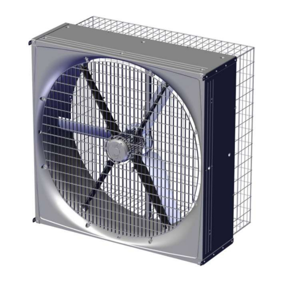
BF 50 LPC -3 Recirculation 1 Product description BF 50 recirculation is a direct-driven corrosion-resistant recirculation fan. BF 50 recirculation is supplied without safety net - these can be ordered as accessories. The recirculation fan is available in several different versions focusing on low power consumption, as well as standard versions. -
Page 7: Product Survey
BF 50 LPC -3 Recirculation 2 Product survey 2.1 BF 50 recirculation fan 2.1.1 Type key BF 50 ON/OFF recirc. 400V3 50Hz 1.5hp Fan name Blue fan Fan size Impeller diameter in inches” Fan type ON/OFF AC fan LPC fan... - Page 8 BF 50 LPC -3 Recirculation 435446 BF 50 LPC -3 recirc. LE 230V1 50/60Hz Safety net must be mounted to comply with CE marking, in countries where this is required. LPC motor controller PM motor 1.5 kW. 0.7 m motor cable.
-
Page 9: Accessories
435460 BF 50 mounting brackets f/recirculation The mounting bracket is used for recirculation where the fan hangs from the ceiling. Supplied with screws for mounting on the fan. SKOV A/S do not supply other mounting parts. One for each fan. -
Page 10: Mounting Guide
BF 50 LPC -3 Recirculation 3 Mounting guide 3.1 Recommended tools A list of the recommended tools for mounting purposes can be seen below. Item Description Cordless drill Screwdriver bits Drill kit Utility knife Marker pen Torque wrench Tape measure... -
Page 11: Removal Of Transport Bracket
BF 50 LPC -3 Recirculation 3.2 Removal of transport bracket On the recirculation fan the red transport bracket is placed between the impeller and the center pillar. Twist the transport bracket out from the center pillar. Remove transport brackets from the fan. -
Page 12: Mounting Of Accessories
BF 50 LPC -3 Recirculation 3.3 Mounting of accessories 3.3.1 Mounting of bracket for recirculation Place the 4 brackets as shown. The two brackets that are similar must be placed diagonally. Mark 6 holes for each of the 4 brackets. -
Page 13: Mounting Of Inside Safety Net
BF 50 LPC -3 Recirculation 3.3.2 Mounting of inside safety net If a safety net has not been selected, a safety guard must be established. The requirements of the International Standard for Safety of machinery ISO 13857 shall be complied with. -
Page 14: Mounting Of Outside Safety Net
BF 50 LPC -3 Recirculation 3.3.3 Mounting of outside safety net If a safety net has not been selected, a safety guard must be established. The requirements of the International Standard for Safety of machinery ISO 13857 shall be complied with. -
Page 15: Installation Guide
4.1.3 Overvoltage protection SKOV A/S equipment are protected for high level of surge transient, but in some cases, specially in areas with frequent lightning strikes and power outage, additional protection is necessary. To reduce the risk of damaging the electronic equipment by large surge overvoltage, it is therefore recommended, always to install Surge Pro- tection Devices (SPD) in the mains supply. -
Page 16: Position Of Motor Controller/Frequency Converter
BF 50 LPC -3 Recirculation 4.1.4 Position of motor controller/frequency converter Motor controller/frequency converter must not be built- in or covered and must be mounted on a solid, level surface. In order to uphold protection classifications, access and cooling, the motor controller/frequency converter must be positioned as shown in section Mounting distances for the motor controller/frequency converter [} 16]. -
Page 17: Cabling To Connection Box And Lpc Motor Controller
BF 50 LPC -3 Recirculation 4.1.7 Cabling to connection box and LPC motor controller LPC motor controller Connection box Power supply isolator Example of cabling to connection box and LPC motor controller. Technical User Guide... -
Page 18: Connection In The Lpc Motor Controller/Frequency Converter
BF 50 LPC -3 Recirculation 4.2 Connection in the LPC motor controller/frequency converter Supply terminals one-phase (L1/L, L2/N). Three-phase (L1/L, L2/N, L3) Screw for ground wire Motor connection terminals (U, W, V) Screw for ground wire Shield connection to fan cable... -
Page 19: Terminals For One-Phase Supply
BF 50 LPC -3 Recirculation 4.2.1 Terminals for one-phase supply Supply one-phase. L1/L = phase L2/N = neutral Mount the supplied cable clip on the ground wire and mount it under the ground screw. 4.2.2 Terminals for three-phase supply Source three-phase. -
Page 20: Signal Terminals
BF 50 LPC -3 Recirculation 4.2.4 Signal terminals *Ground Stop = open Start = GND (Short-circuit connection between terminal 8 and GND) *Ground (connected to ground screw) Normal = open Reverse = GND (Short-circuit connection between terminal 15 and GND) -
Page 21: Led Indication On Display
BF 50 LPC -3 Recirculation 4.3 LED indication on display To display certain warnings, the motor controller has a built-in 6-digit 7-segment LED display. LED segments Display Meaning a, b, c, d, e, f All flashing Overload, the motor output current... - Page 22 BF 50 LPC -3 Recirculation H 50.0 Motor controller is activated / running, display shows the output frequency [Hz]. A 2.3 Press Navigate. The display will show the motor cur- rent [A]. P 1.50 Press Navigate. The display will show the motor power [kW].
-
Page 23: Change 10-0 V Analog Input Into 0-10 V
BF 50 LPC -3 Recirculation 4.4.1 Change 10-0 V analog input into 0-10 V The factory setting is 10-0 V. StoP Press and hold the Navigate key for more than 2 sec- onds. P-16 Press Up and select P-16 U 10-0 Press Navigate. - Page 24 BF 50 LPC -3 Recirculation P-16 Press Navigate. The new setting is now saved. StoP Press and hold the Navigate key for more than 2 sec- onds to return to operating mode. Technical User Guide...
-
Page 25: General Information About Circuit Diagrams
BF 50 LPC -3 Recirculation 4.5 General information about circuit diagrams Symbols are in accordance with the IEC/EN 60617 standard. The classification of the symbols ("letter codes") on the symbols is in accordance with the IEC/EN 81346-2 stan- dard. Reference designations are in accordance with IEC/EN 81346-1:2001 structuring principles and reference des- ignations. -
Page 26: Cable Plans And Circuit Diagrams
BF 50 LPC -3 Recirculation 4.6 Cable plans and circuit diagrams 4.6.1 BF 50 LPC -3 recirculation 1x230 V 4.6.1.1 Cable plan Controller LPC fan 1x230 V LPC motor controller Power supply isolator Connection box 4.6.1.2 Terminals in LPC 1x230 V fan... -
Page 27: Circuit Diagram
BF 50 LPC -3 Recirculation 4.6.1.3 Circuit diagram Analog signal default 10-0 V, if you want to change the analog signal, see section Signal terminals Example of terminal number For correct connection see the setup menu Show connection in controller... -
Page 28: Bf 50 Lpc -3 Recirculation 3X400 V
BF 50 LPC -3 Recirculation 4.6.2 BF 50 LPC -3 recirculation 3x400 V 4.6.2.1 Cable plan Controller LPC fan 3x400 V LPC motor controller Power supply isolator Connection box 4.6.2.2 Terminals in LPC 3x400 V fan Internal External Technical User Guide... -
Page 29: Circuit Diagram
BF 50 LPC -3 Recirculation 4.6.2.3 Circuit diagram Analog signal default 10-0 V, if you want to change the analog signal, see section Signal terminals Example of terminal number For correct connection see the setup menu Show connection in the controller... -
Page 30: Bf 50 Lpc -3 Recirculation 3X230 V
BF 50 LPC -3 Recirculation 4.6.3 BF 50 LPC -3 recirculation 3x230 V 4.6.3.1 Cable plan Controller LPC fan 3x230 V LPC motor controller Power supply isolator Connection box 4.6.3.2 Terminals in LPC 3x230 V fan Internal External Technical User Guide... -
Page 31: Circuit Diagram
BF 50 LPC -3 Recirculation 4.6.3.3 Circuit diagram Analog signal default 10-0 V, if you want to change the analog signal, see section Signal terminals Example of terminal number For correct connection see the setup menu Show connection in the controller... -
Page 32: Maintenance Instructions
When washing the inside of the ducts, fan blades must stand still. Remember that fans do not stand high-pressure cleaning. If the inside of the duct needs to be cleaned extra thoroughly SKOV A/S recommends washing from above. When washing the fan, the fan must run around. -
Page 33: Trouble Shooting Instructions
BF 50 LPC -3 Recirculation 6 Trouble shooting instructions Remember to shut the fan off at the power supply isolator prior to troubleshooting. Wait 10 minutes for the capacitors to discharge to a safe voltage level before servicing and trou- bleshooting. - Page 34 Defective thermistor on the Motor controller defective. Replace motor controller. eat sink. dAtA-F Internal memory error (IO). Press the stop key. Contact SKOV A/S Fan-F Cooling fan error (IP66 Motor controller defective. Replace motor controller. only). O-hEAt Internal temperature of mo- Check that the ambient temperature and distance re- tor controller too high.
-
Page 35: Technical Data
BF 50 LPC -3 Recirculation 7 Technical data 7.1 BF 50 LPC -3 recirculation 1x230 V 435446 BF 50 LPC recirc. LE 230V1 50/60Hz Electrical V AC 230 +/- 10% Rated voltage V AC 180 – 253 Operating voltage For supply voltages below the rated voltage range, a reduction of the fan’s RPM may occur depending on the load and ambient... - Page 36 BF 50 LPC -3 Recirculation 435446 BF 50 LPC recirc. LE 230V1 50/60Hz Environment °C ÷ 20 to + 40 Temperature, operation °C ÷ 15 to + 50 Start temperature °C ÷ 40 to + 60 Storage temperature % RH 10 –...
-
Page 37: Bf 50 Lpc -3 Recirculation 3X400 V
BF 50 LPC -3 Recirculation 7.2 BF 50 LPC -3 recirculation 3x400 V 435414 BF 50 LPC -3 recirc. LE 400V3 50/60Hz Electrical V AC 400 +/- 10% Rated voltage V AC 310 – 480 Operating voltage For supply voltages below the rated voltage range, a reduction of the fan’s RPM may occur depending on the load and ambient... - Page 38 BF 50 LPC -3 Recirculation 435414 BF 50 LPC -3 recirc. LE 400V3 50/60Hz °C ÷ 15 to + 50 Start temperature °C ÷ 40 to + 60 Storage temperature % RH 10 - 95 Ambient humidity, operation Motor controller: IP 66. Fan motor: IP 65...
-
Page 39: Bf 50 Lpc -3 Recirculation 3X230 V
BF 50 LPC -3 Recirculation 7.3 BF 50 LPC -3 recirculation 3x230 V 435447 BF 50 LPC -3 recirc. LE 230V3 50/60Hz Electrical V AC 230 +/- 10% Rated voltage V AC 175 – 270 Operating voltage For supply voltages below the rated voltage range, a reduction of the fan’s RPM may occur depending on the load and ambient... - Page 40 BF 50 LPC -3 Recirculation 435447 BF 50 LPC -3 recirc. LE 230V3 50/60Hz °C ÷ 15 to + 50 Start temperature °C ÷ 40 to + 60 Storage temperature % RH 10 - 95 Ambient humidity, operation Motor controller: IP 66. Fan motor: IP 65...
-
Page 41: Dimensioned Sketch
BF 50 LPC -3 Recirculation 7.4 Dimensioned sketch 7.4.1 BF 50 recirculation 7.4.2 Outside safety net Outside safety net Technical User Guide... -
Page 42: Lpc Motor Controller
BF 50 LPC -3 Recirculation 7.4.3 LPC motor controller LPC motor controller 148.5 Technical User Guide... - Page 44 SKOV A/S • Hedelund 4 • Glyngøre • DK-7870 Roslev Tel. +45 72 17 55 55 • www.skov.com • E-mail: skov@skov.dk...
Need help?
Do you have a question about the BF 50 LPC and is the answer not in the manual?
Questions and answers