Table of Contents
Advertisement
Quick Links
BF 50 LPC -3
Wall Fans
Technical User Guide
English For other language variants of this document we refer to:
Español Para otras variantes del idioma de este documento, visite:
Français Pour les versions dans d'autres langues de ce document veuillez consulter:
http://docs.skov.com/1241
604490 • 2022-03-01
Advertisement
Table of Contents

Related Manuals for Skov BF 50 LPC-3


Summary of Contents for Skov BF 50 LPC-3
- Page 1 Technical User Guide English For other language variants of this document we refer to: Español Para otras variantes del idioma de este documento, visite: Français Pour les versions dans d'autres langues de ce document veuillez consulter: http://docs.skov.com/1241 604490 • 2022-03-01...
- Page 3 Note • All rights belong to SKOV A/S. No part of this manual may be reproduced in any manner whatsoever without the expressed written permission of SKOV A/S in each case.
-
Page 4: Table Of Contents
BF 50 LPC -3 1 Product description............................ 7 2 Product survey ............................... 8 BF 50 wall fans .......................... 9 2.1.1 Type key ............................ 9 Accessories.......................... 11 3 Mounting guide............................. 13 Recommended tools........................ 13 Placement of BF 50 ......................... 15 Preparing hole in wall...................... 15 3.3.1 Necessary space for BF 50 with LPC motor controller .............. - Page 5 BF 50 LPC -3 4.6.1 BF 50 LPC actuator time-controlled................... 52 4.6.2 BF 50 LPC actuator stepless ..................... 52 Connection of extra 24 V power supply................. 53 General information about circuit diagrams ................. 54 4.8.1 Color code.......................... 54 4.8.2 Power supply isolator......................... 54 4.8.3 Letter code ..........................
- Page 6 BF 50 LPC -3 Actuators .......................... 83 Metal and plastic parts ...................... 84 Light traps .......................... 85 Number of wall fans in a container .................. 86 Dimensioned sketch ........................ 87 7.8.1 BF 50 LPC -3 .......................... 87 7.8.2 LPC motor controller ........................ 88 7.8.3 Light trap ............................
-
Page 7: Product Description
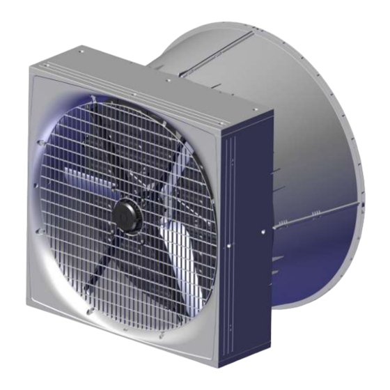
BF 50 LPC -3 1 Product description BF 50 is a direct driven corrosion-free wall fan. BF 50 is available with air controlled and motor controlled shutters. The fan is available in several different versions focusing on low power consumption, as well as standard ver- sions. -
Page 8: Product Survey
BF 50 LPC -3 2 Product survey Technical User Guide... -
Page 9: Bf 50 Wall Fans
BF 50 LPC -3 2.1 BF 50 wall fans 2.1.1 Type key BF 50 ON/OFF EL HF 400V3 50Hz 1.5hp TH Fan name Blue fan Fan size Impeller diameter in inches” Fan type AC fan ON/OFF LPC fan Shutter type Motor controlled Air controlled ON/OFF... - Page 10 BF 50 LPC -3 435421 BF 50 LPC -3 ON/OFF HF 400V3 50/60Hz 435424 BF 50 LPC -3 ON/OFF LE 400V3 50/60Hz Fan control method - variable ON/OFF. 435422 BF 50 LPC -3 VAR HF 400V3 50/60H 435423 BF 50 LPC -3 VAR LE 400V3 50/60Hz Fan control method - stepless.
-
Page 11: Accessories
BF 50 LPC -3 2.2 Accessories 435397 BF 50 safety net outside wo/cone, A2 435398 BF 50 safety net outside wo/cone, galv The outside safety net is used on BF 50 without cone where extra safety is required. Supplied with mounting parts. One for each fan. - Page 12 Insulation plate cannot be immediately used, if the air controlled shutter is mounted inside. If this solution is required, a frame for mounting insulation plate must be established. Such a frame is not supplied by SKOV but must be produced locally.
-
Page 13: Mounting Guide
BF 50 LPC -3 3 Mounting guide Check that the parts ordered are present and undamaged before starting work. Please read through the entire guide before starting assembly and fitting. If the BF 50 is installed in areas with risk of ice/snow slide, precautions must be made to avoid damage to the BF 50. - Page 14 BF 50 LPC -3 Item Description Foam gun Ladder Jigsaw Socket wrench set Spirit level Try square Technical User Guide...
-
Page 15: Placement Of Bf 50
BF 50 LPC -3 3.2 Placement of BF 50 BF 50 must be placed in the livestock house according to the drawing supplied. Contact SKOV A/S if major changes are made. Check that all BF 50 can be placed freely in relation to other housing equipment upon agreement with the client. -
Page 16: Measurements For Square Hole In Wall
BF 50 LPC -3 3.3.3 Measurements for square hole in wall The dimensions below are given in mm . Recommended measurements for individual mounting of BF 50 wall fan. (A) Minimum distance is 550 mm, when mounting the LPC motor controller above BF 50. (B) Minimum distance is 300 mm, when mounting the LPC motor controller between BF 50. -
Page 17: Measurements For Square Hole In Wall With Cone
BF 50 LPC -3 3.3.4 Measurements for square hole in wall with cone The dimensions below are given in mm. Recommended measurements for individual mounting of BF 50 wall fan with mounted cone. (A) Minimum distance is 550 mm, when mounting the LPC motor controller above BF 50. (B) Minimum distance is 300 mm, when mounting the LPC motor controller between BF 50. -
Page 18: Measure And Saw Out The Holes
BF 50 LPC -3 3.4 Measure and saw out the holes Remember to always use a spirit level. Drill 10 mm holes all the way through the wall. Cut the holes. Technical User Guide... -
Page 19: Drainage Holes
BF 50 LPC -3 3.5 Drainage holes Yellow Please note that the yellow blanking plug must be at the top. Black If parts of BF 50 are outside the wall, on the outside, it is recommended to drill 4 pcs. 5 mm drain holes in the bottom on the four markings. -
Page 20: Mounting In Wall
BF 50 LPC -3 3.6 Mounting in wall Lead the cables into the livestock house. Make sure that there is free space for cables. Measure from the top of BF 50 down (A) make a hole in the wall for the cables as the bending radius of the fan cables is 50 mm. -
Page 21: Mounting With Four Brackets
BF 50 LPC -3 3.6.1 Mounting with four brackets Mount 2 brackets (not supplied) in the bottom of BF 50 to fit the wall thickness. Place BF 50 in the wall. Use wedges to center BF 50 in the hole. Tip BF 50 so that the 2 internal brackets can be mounted. -
Page 22: Mounting Of Four Angle Bars
BF 50 LPC -3 3.6.2 Mounting of four angle bars Mount the 4 angle bars (not supplied) on BF 50 to fit the wall thickness. Place BF 50 in the wall. Technical User Guide... -
Page 23: Mounting In Wooden Frame
BF 50 LPC -3 3.6.3 Mounting in wooden frame Mount the wooden frame with brackets (not supplied). Place BF 50 in the wall. Technical User Guide... -
Page 24: Foaming
Screw BF 50 into the wall with 8 screws, with a length of minimum 150 mm. 3.6.4 Foaming SKOV A/S recommends using single-component polyurethane foam or similar. Check before foaming how much the foam expands. An external angle bracket can be used to for completion (not supplied by SKOV A/S). - Page 25 BF 50 LPC -3 Wet the faces with water from a mist sprayer before pro- ceeding with the foaming. Foam around BF 50 as shown in the drawing. Foam the wall fan’s corners and approx. 100 mm to each side foam the entire depth of the BF 50.
- Page 26 BF 50 LPC -3 In the middle part, it is essential only to foam along the edge, as the foam may otherwise cause BF 50 to warp. Push the foam in against BF 50 after the foam has dried a little to allow adequate space for resealing. Wet the foam again with water from a mist sprayer.
-
Page 27: Pointing
BF 50 LPC -3 3.6.5 Pointing SKOV A/S recommends Sikaflex 111 Stick & Seal. Complete by applying a sealing edge both internally and externally when the foam is dry. Apply a sealing edge along the angle bracket, as shown in the drawing. -
Page 28: Removing The Transport Bracket
BF 50 LPC -3 3.7 Removing the transport bracket On BF 50 LPC and EL the red transport bracket is lo- cated behind the impeller hub. Cut the cable ties. Wrench the transport brackets apart. Remove cable ties and transport brackets from the fan. On BF 50 AIR the red transport bracket is placed be- tween the impeller and the center pillar. -
Page 29: Mounting Of Inside Safety Net
BF 50 LPC -3 3.8 Mounting of inside safety net Make sure that the net is turned as shown in the draw- ing. Mount the inside safety net on the wall fan using 8 of the screws enclosed (do not tighten to more than 2 Nm). Mount the enclosed 4 straps and screws. -
Page 30: Manual Opening Of Motor Controlled Shutter
BF 50 LPC -3 3.9 Manual opening of motor controlled shutter Remove the yellow blanking plug. Press on the yellow actuator split with a screwdriver. Technical User Guide... - Page 31 BF 50 LPC -3 The shutter can now be opened manually. Remember to shut off the fan at the power supply isolator prior to mounting of manual opening. After manual opening. Open the shutters by moving the actuator into its ex- treme position.
- Page 32 BF 50 LPC -3 Mount the yellow actuator split in the actuator and center column. Mount the rubber plug in the shutter. Technical User Guide...
-
Page 33: Mounting Of Accessories
BF 50 LPC -3 3.10 Mounting of accessories 3.10.1 Cone Consists of 4 identical parts. Ensure the tongue and groove at the base are in line. Click the sides together. Hang the cone on the wall fan. Mount the assembled cone on the wall fan using the en- closed screws, female connectors and self-locking nuts. -
Page 34: Outside Safety Net
BF 50 LPC -3 3.10.2 Outside safety net If a BF 50 outside safety net has not been selected, a safety guard must be established. The requirements of the International Standard for Safety of machinery ISO 13857 shall be complied with. 3.10.2.1 Without cone Assemble the safety net outside with the included strips. -
Page 35: With Cone
BF 50 LPC -3 When mounting on an air controlled shutter, pre-drill with a 4.5 mm drill on the side of the shutter. Mount the safety net outside on the air controlled shutter using the clips and screws enclosed (do not tighten to more than 2 Nm). -
Page 36: Insulation Plate
BF 50 LPC -3 3.10.3 Insulation plate Mount brackets for the insulation plate on the fan with the 2 screws. Mount the sealing profile on the insulation plate. Drill a 12 mm hole in the center of the insulation plate. The sealing profile must be facing the wall fan. -
Page 37: Shading Kit
BF 50 LPC -3 3.10.4 Shading kit Mount the top bracket on the plate with 2 screws. Mount 2 bottom brackets on the plate with 2 screws in each. Mount the top bracket on the wall using 2 screws. Mount 2 bottom brackets on the wall fan with 2 screws in each. - Page 38 BF 50 LPC -3 Screw 2 eye joiners onto the pull rod. Mount eye joiner in top bracket mounted on wall with 1 x M6x20 screw and M6 washer. Mount plate in the bottom bracket on the wall fan. Mount eye joiner in top bracket on plate with split pin. Technical User Guide...
-
Page 39: Light Trap
BF 50 LPC -3 3.10.5 Light trap The sealing profile must be facing BF 50. Mount the mounting fittings on the wall and on the light trap. Hang the light trap on the wall by engaging the 2 sus- pension brackets. Technical User Guide... -
Page 40: Installation Guide
4.1.3 Overvoltage protection SKOV A/S equipment are protected for high level of surge transient, but in some cases, specially in areas with frequent lightning strikes and power outage, additional protection is necessary. To reduce the risk of damaging the electronic equipment by large surge overvoltage, it is therefore recommended, always to install Surge Pro- tection Devices (SPD) in the mains supply. -
Page 41: Position Of Motor Controller/Frequency Converter
BF 50 LPC -3 4.1.4 Position of motor controller/frequency converter Motor controller/frequency converter must not be built- in or covered and must be mounted on a solid, level surface. In order to uphold protection classifications, access and cooling, the motor controller/frequency converter must be positioned as shown in section Mounting distances for the motor controller/frequency converter [} 41]. -
Page 42: Cabling To Connection Box And Lpc Motor Controller
BF 50 LPC -3 4.1.7 Cabling to connection box and LPC motor controller LPC motor controller Connection box Power supply isolator Example of cabling to connection box and LPC motor controller. Technical User Guide... -
Page 43: Connection In The Lpc Motor Controller/Frequency Converter
BF 50 LPC -3 4.2 Connection in the LPC motor controller/frequency converter Supply terminals one-phase (L1/L, L2/N). Three-phase (L1/L, L2/N, L3) Screw for ground wire Motor connection terminals (U, W, V) Screw for ground wire Shield connection to fan cable Signal terminals Factory mounted ground wire Bottom plate with cable glands... -
Page 44: Terminals For One-Phase Supply
BF 50 LPC -3 4.2.1 Terminals for one-phase supply Supply one-phase. L1/L = phase L2/N = neutral Mount the supplied cable clip on the ground wire and mount it under the ground screw. 4.2.2 Terminals for three-phase supply Supply three-phase. L1/L = phase L2/N = phase L3 = phase... -
Page 45: Signal Terminals
BF 50 LPC -3 4.2.4 Signal terminals *Ground Stop = open Start = GND (Jumper connection between terminal 8 and GND) *Ground (connected to ground screw) Normal = open Reverse = GND (Jumper connection between terminal 15 and GND) *Ground Signal from house controller (factory setting 10-0 V) in case of change, see section 4.4.1 Max. -
Page 46: Led Indication On Display
BF 50 LPC -3 4.3 LED indication on display To display certain warnings, the motor controller has a built-in 6-digit 7-segment LED display. LED segments Display Meaning a, b, c, d, e, f All flashing Overload, the motor output current exceeds the maximum limit a and f Flashes alternately... - Page 47 BF 50 LPC -3 H 50.0 Motor controller is activated / running, display shows the output frequency [Hz]. A 2.3 Press Navigate. The display will show the motor cur- rent [A]. P 1.50 Press Navigate. The display will show the motor power [kW].
-
Page 48: Change 10-0 V Analog Input Into 0-10 V
BF 50 LPC -3 4.4.1 Change 10-0 V analog input into 0-10 V The factory setting is 10-0 V. StoP Press and hold the Navigate key for more than 2 sec- onds. P-16 Press Up and select P-16 U 10-0 Press Navigate. - Page 49 BF 50 LPC -3 P-16 Press Navigate. The new setting is now saved. StoP Press and hold the Navigate key for more than 2 sec- onds to return to operating mode. Technical User Guide...
-
Page 50: Emergency Opening For Bf 50 Actuator - House Controller
BF 50 LPC -3 4.5 Emergency opening for BF 50 actuator – house controller If emergency unlock for the shutter motor is required, it must be powered by an F6 24V power supply via the computer in the livestock house. For fans that do not require emergency unlock, the shutter motor is powered by an external 24 V power supply without battery backup. -
Page 51: Fan Not Active At Power Failure
BF 50 LPC -3 4.5.2 Fan not active at power failure To deactivate the fan at a power failure, select | Installation | Manual installation | Cli- mate | Air outlet | Tunnel outlet and after that Fans active at failure in the menu in the climate controller. -
Page 52: Connection To Actuator
BF 50 LPC -3 4.6 Connection to actuator 4.6.1 BF 50 LPC actuator time-controlled Input signal Open/Closed Flaps Open 45 sec. Close 22 sec. Delayed opening 15 sec. LPC actuator time-controlled 4.6.2 BF 50 LPC actuator stepless Input signal Closed Open 10 V Analog out... -
Page 53: Connection Of Extra 24 V Power Supply
BF 50 LPC -3 4.7 Connection of extra 24 V power supply Internal power supply (A) may only be used to supply factory-installed modules. In case of a greater power consumption than 0.4 A from the main module (B) and 0.4 A from the I/O modules (C) an extra power supply (D) must be used and possibly (E). -
Page 54: General Information About Circuit Diagrams
BF 50 LPC -3 4.8 General information about circuit diagrams Symbols are pursuant to the IEC/EN 60617 standard. The classification of the symbols ("letter codes") on the symbols is pursuant to the IEC/EN 81346-2 standard. Reference designations are in accordance with IEC/EN 81346-1:2001 structuring principles and reference des- ignations. -
Page 55: Cable Plans And Circuit Diagrams
BF 50 LPC -3 4.9 Cable plans and circuit diagrams 4.9.1 Circuit diagram for OFF/AUTO/ON switch 4.9.1.1 BF 50 LPC -3 Example of terminal number For correct connection see the setup menu Show connection in controller LPC motor controller Actuator 4.9.2 Circuit diagram for emergency opening 4.9.2.1 BF 50 LPC -3 Regarding circuit diagram for BF 50 LPC -3, see section Emergency opening for BF 50 actuator –... -
Page 56: Bf 50 Lpc -3 With Reverse (1X230 V)
BF 50 LPC -3 4.9.3 BF 50 LPC -3 with reverse (1x230 V) 4.9.3.1 Cable plan Controller Key breaker LPC fan 1x230 V LPC motor controller Power supply Connection box isolator LPC actuator stepless 4.9.3.2 Circuit diagram Power supply from emergency opening 0V-1 = Q1 terminal in controller. Power supply from emergency opening 24V-12 = F6 terminal in emergency opening. -
Page 57: Bf 50 Lpc -3 With Alarm Relay (1X230 V)
BF 50 LPC -3 4.9.4 BF 50 LPC -3 with alarm relay (1x230 V) 4.9.4.1 Cable plan Controller LPC fan 1x230 V LPC motor controller Power supply isolator Connection box LPC actuator stepless Alarm 4.9.4.2 Circuit diagram Power supply from emergency opening 0V-1 = Q1 terminal in controller. Power supply from emergency opening 24V-12 = F6 terminal in emergency opening. -
Page 58: Bf 50 Lpc -3 Bf 50 Lpc -3 1X230 V Variable On/Off (435444)
BF 50 LPC -3 4.9.5 BF 50 LPC -3 BF 50 LPC -3 1x230 V variable ON/OFF (435444) 4.9.5.1 Cable plan Controller LPC fan 1x230 V LPC motor controller Power supply isolator Connection box LPC actuator time-controlled 4.9.5.2 Terminals in LPC 1x230 V fan Internal External Technical User Guide... -
Page 59: Circuit Diagram
BF 50 LPC -3 4.9.5.3 Circuit diagram Power supply from emergency opening 0V-1 = Q1 terminal in controller. Power supply from emergency opening 24V-12 = F6 terminal in emergency opening. Example of terminal number For correct connection see the setup menu Show connection in controller Connection box LPC 1 x 230 V... -
Page 60: Bf 50 Lpc -3 1X230 V Stepless (435443)
BF 50 LPC -3 4.9.6 BF 50 LPC -3 1x230 V stepless (435443) 4.9.6.1 Cable plan Controller LPC fan 1x230 V LPC motor controller Power supply Connection box isolator LPC actuator stepless 4.9.6.2 Terminals in LPC 1x230 V fan Internal External Technical User Guide... -
Page 61: Circuit Diagram
BF 50 LPC -3 4.9.6.3 Circuit diagram Power supply from emergency opening 0V-1 = Q1 terminal in controller. Power supply from emergency opening 24V-12 = F6 terminal in emergency opening. Example of terminal number For correct connection see the setup menu Show connection in controller Connection box LPC 1 x 230 V... -
Page 62: Bf 50 Lpc -3 3X400 V Variable On/Off (435421/435424)
BF 50 LPC -3 4.9.7 BF 50 LPC -3 3x400 V variable ON/OFF (435421/435424) 4.9.7.1 Cable plan Controller LPC fan 3x400 V LPC motor controller Power supply isolator Connection box LPC actuator time-controlled 4.9.7.2 Terminals in LPC 3x400 V fan Internal External Technical User Guide... -
Page 63: Circuit Diagram
BF 50 LPC -3 4.9.7.3 Circuit diagram Power supply from emergency opening 0V-1 = Q1 terminal in controller. Power supply from emergency opening 24V-12 = F6 terminal in emergency opening. Example of terminal number For correct connection see the setup menu Show connection in controller Connection box LPC 3 x 400 V... -
Page 64: Bf 50 Lpc -3 3X400 V Stepless (435422/435423)
BF 50 LPC -3 4.9.8 BF 50 LPC -3 3x400 V stepless (435422/435423) 4.9.8.1 Cable plan Controller LPC fan 3x400 V LPC motor controller Power supply isolator Connection box LPC actuator stepless 4.9.8.2 Terminals in LPC 3x400 V fan Internal External Technical User Guide... -
Page 65: Circuit Diagram
BF 50 LPC -3 4.9.8.3 Circuit diagram Power supply from emergency opening 0V-1 = Q1 terminal in controller. Power supply from emergency opening 24V-12 = F6 terminal in emergency opening. Example of terminal number For correct connection see the setup menu Show connection in controller Connection box LPC 3 x 400 V... -
Page 66: Bf 50 Lpc -3 3X230 V Variable On/Off (435412)
BF 50 LPC -3 4.9.9 BF 50 LPC -3 3x230 V variable ON/OFF (435412) 4.9.9.1 Cable plan Controller LPC fan 3x230 V LPC motor controller Power supply isolator Connection box LPC actuator time-controlled 4.9.9.2 Terminals in LPC 3x230 V fan Internal External Technical User Guide... -
Page 67: Circuit Diagram
BF 50 LPC -3 4.9.9.3 Circuit diagram Power supply from emergency opening 0V-1 = Q1 terminal in controller. Power supply from emergency opening 24V-12 = F6 terminal in emergency opening. Example of terminal number For correct connection see the setup menu Show connection in controller Connection box LPC 3 x 230 V... -
Page 68: Bf 50 Lpc -3 3X230 V Stepless (435411)
BF 50 LPC -3 4.9.10 BF 50 LPC -3 3x230 V stepless (435411) 4.9.10.1 Cable plan Controller LPC fan 3x230 V LPC motor controller Power supply isolator Connection box LPC actuator stepless 4.9.10.2 Terminals in LPC 3x230 V fan Internal External Technical User Guide... -
Page 69: Circuit Diagram
BF 50 LPC -3 4.9.10.3 Circuit diagram Power supply from emergency opening 0V-1 = Q1 terminal in controller. Power supply from emergency opening 24V-12 = F6 terminal in emergency opening. Example of terminal number For correct connection see the setup menu Show connection in controller Connection box LPC 3 x 230 V... -
Page 70: Maintenance Instructions
When washing the inside of the ducts, fan blades must stand still. Remember that fans do not stand high-pressure cleaning. If the inside of the duct needs to be cleaned extra thoroughly SKOV A/S recommends washing from above. When washing the fan, the fan blades must turn around. -
Page 71: Trouble Shooting Instructions
BF 50 LPC -3 6 Trouble shooting instructions Remember to shut the fan off at the power supply isolator prior to troubleshooting. Wait 10 minutes for the capacitors to discharge to a safe voltage level before servicing and trou- bleshooting. Failure to observe this precaution could result in serious injury or loss of life. - Page 72 Defective thermistor on the Motor controller defective. Replace motor controller. eat sink. dAtA-F Internal memory error (IO). Press the stop key. Contact SKOV A/S Fan-F Cooling fan error (IP66 Motor controller defective. Replace motor controller. only). O-hEAt Internal temperature of mo- Check that the ambient temperature and distance re- tor controller too high.
-
Page 73: Resetting Errors
BF 50 LPC -3 6.1 Resetting errors When the motor controller stops and an error message is displayed, it can be reset in one of the following ways: • Disconnect the supply voltage for 10 minutes. Reconnect the supply voltage. •... -
Page 74: Technical Data
BF 50 LPC -3 7 Technical data 7.1 BF 50 LPC -3 1x230 V Air output and efficiency in parenthesis are for wall fans with cone. 435444 BF 50 LPC -3 ON/OFF LE 435443 BF 50 LPC -3 VAR LE Electrical V AC 230 +/- 10%... - Page 75 Power consumption at -10 Pa /kWh 29300 (33500) Specific output at -10 Pa Watt/1000 34 (30) Specific energy at -10 Pa SKOV A/S Testing body Environment °C ÷ 20 to + 40 Temperature, operation °C ÷ 15 to + 50 Start temperature °C...
-
Page 76: Erp/Ecodesign Bf 50 Lpc -3 1X230 V
ErP 2015 (N40) Ecodesign Efficiency classification 58.8 Efficiency (η) Measurement setup Static Fan efficiency VSD required 2022 Year of production SKOV A/S Name of manufacturer 435444 435443 Item number 1.356 Motor power input 7.40 Flow rate Optimum pressure Revolutions per minute... -
Page 77: Bf 50 Lpc -3 3X400 V
BF 50 LPC -3 7.2 BF 50 LPC -3 3x400 V Air output and efficiency in parenthesis are for wall fans with cone. 435421 BF 50 LPC -3 ON/OFF 435424 BF 50 LPC -3 ON/OFF HF / 435422 BF 50 LPC -3 VAR LE / 435423 BF 50 LPC -3 VAR Electrical V AC... - Page 78 /kWh 25100 (28600) 29900 (34200) Specific output at -10 Pa Watt/1000 40 (35) 33 (29) Specific energy at -10 Pa SKOV A/S Testing body Environment °C ÷ 20 to + 40 Temperature, operation °C ÷ 15 to + 40 Start temperature °C...
-
Page 79: Erp/Ecodesign Bf 50 Lpc -3 3X400 V
Ecodesign Efficiency classification 59.0 60.0 Efficiency (η) Measurement setup Static Fan efficiency VSD required 2022 Year of production SKOV A/S Name of manufacturer 435421 / 435422 435424 / 435423 Item number 1.789 1.354 Motor power input 8.25 7.86 Flow rate... -
Page 80: Bf 50 Lpc -3 3X230 V
BF 50 LPC -3 7.3 BF 50 LPC -3 3x230 V Air output and efficiency in parenthesis are for wall fans with cone. 435412 BF 50 LPC -3 ON/OFF LE 435411 BF 50 LPC -3 VAR LE Electrical V AC 230 +/- 10% Rated voltage V AC... - Page 81 Power consumption at -10 Pa /kWh 29400 (33900) Specific output at -10 Pa Watt/1000 34 (30) Specific energy at -10 Pa SKOV A/S Testing body Environment °C ÷ 20 to + 40 Temperature, operation °C ÷ 15 to + 50 Start temperature °C...
-
Page 82: Erp/Ecodesign Bf 50 Lpc -3 3X230 V
ErP 2015 (N40) Ecodesign Efficiency classification 59.9 Efficiency (η) Measurement setup Static Fan efficiency VSD required 2022 Year of production SKOV A/S Name of manufacturer 435412 435411 Item number 1.369 Motor power input 7.68 Flow rate Optimum pressure Revolutions per minute... - Page 83 BF 50 LPC -3 7.4 Actuators 524116 524118 LPC actuator time-controlled LPC actuator stepless Electrical V DC Rated voltage V DC 16 – 28 16 – 28 Operating voltage Max. current consump- tion at 24 V DC power supply pcs. Number of actuators on power supply 24V 2.1/4.2A...
- Page 84 BF 50 LPC -3 7.5 Metal and plastic parts Mechanical Material plastic PP T20 BF 50 box PP T20 BF 50 top and bottom panel PP T20 BF 50 side panel PP T20 BF 50 cone PP GF30 BF 50 center pillar PP T20 BF 50 inside safety net HIPS...
- Page 85 BF 50 LPC -3 7.6 Light traps 50ʺ light trap brown out 50ʺ light trap black out Mechanical Material RAL 9005 Color Fan output The light trap reduces the air output The light trap reduces the air output With cone of the fan by approx 18 % at 0-70 of the fan by approx 35 % at 0-70 Pa pressure difference.
-
Page 86: Number Of Wall Fans In A Container
BF 50 LPC -3 7.7 Number of wall fans in a container Number of wall fans in a container Motor controlled shutter Air controlled shutter 20' DC BF 50 without cone BF 50 with cone 40' HC BF 50 without cone BF 50 with cone Technical User Guide... -
Page 87: Dimensioned Sketch
BF 50 LPC -3 7.8 Dimensioned sketch 7.8.1 BF 50 LPC -3 BF 50 without cone BF 50 with cone Technical User Guide... -
Page 88: Lpc Motor Controller
BF 50 LPC -3 7.8.2 LPC motor controller LPC motor controller 148.5 7.8.3 Light trap 50ʺ brown out / 50ʺ black out Technical User Guide... -
Page 89: Outside Safety Net
BF 50 LPC -3 7.8.4 Outside safety net Outside safety net Technical User Guide... - Page 92 SKOV A/S • Hedelund 4 • Glyngøre • DK-7870 Roslev Tel. +45 72 17 55 55 • www.skov.com • E-mail: skov@skov.dk...
Need help?
Do you have a question about the BF 50 LPC-3 and is the answer not in the manual?
Questions and answers