Table of Contents
Advertisement
Quick Links
Advertisement
Table of Contents

Subscribe to Our Youtube Channel
Related Manuals for Skov BF 50


Summary of Contents for Skov BF 50
- Page 1 BF 50 Shutter Technical User Guide English For other language variants of this document we refer to: Español Para otras variantes del idioma de este documento, visite: Français Pour les versions dans d'autres langues de ce document veuillez consulter: http://docs.skov.com/1241...
- Page 2 The date of change appears from the front and back pages. Note • All rights belong to SKOV A/S. No part of this manual may be reproduced in any manner whatsoever without the expressed written permission of SKOV A/S in each case.
-
Page 3: Table Of Contents
Power supply isolator......................... 31 4.5.3 Letter Code .......................... 31 Cable plans and circuit diagrams................... 32 4.6.1 BF 50 shutter VAR cable plan .................... 32 4.6.2 BF 50 shutter VAR circuit diagram .................... 32 4.6.3 BF 50 shutter ON/OFF cable plan .................... 33 4.6.4... - Page 4 BF 50 Shutter 7.5.1 BF 50 shutter .......................... 39 7.5.2 Light trap ............................ 39 Technical User Guide...
-
Page 5: Product Description
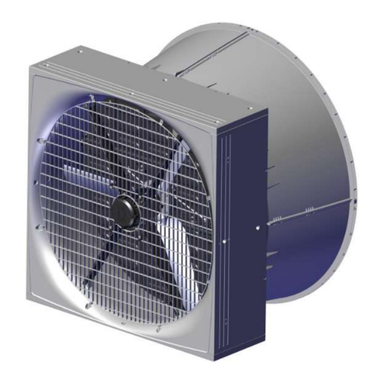
BF 50 Shutter 1 Product description BF 50 shutter is used in SKOV A/S positive pressure systems where the incoming air is filtrated to avoid air- borne diseases from infecting the animals. BF 50 shutter is without fan but with cone and shutter controlled by a stepless or ON/OFF actuator. The shutter is controlled in relation to the amount of air passing through the livestock house while maintaining the positive pressure in the house to prevent unfiltered air from entering though leaks. -
Page 6: Product Survey
435393 BF 50 shutter VAR with actuator and cone BF 50 shutter VAR is used for positive pressure systems. BF 50 shutter VAR is without fan but with cone and shutter controlled by a stepless actuator. The stepless shutter is controlled in relation to the amount of air passing through the house while maintaining the positive pressure in the house to prevent unfiltered air from entering though leaks. -
Page 7: Accessories
BF 50 Shutter 2.2 Accessories 435396 BF 50 safety net outside for cone, A2 The outside safety net for cone is used where extra safety is required. Supplied with mounting parts. 1 per wall fan. 435156 50" light trap brown out Used if dimming is required in the livestock house. -
Page 8: Mounting Guide
Check that the parts ordered are present and undamaged before starting work. Please read through the entire guide before starting assembly and fitting. If the BF 50 is installed in areas with risk of ice/snow slide, precautions must be made to avoid damage to the BF 50. - Page 9 BF 50 Shutter Item Description Foam gun Ladder Jigsaw Socket wrench set Spirit level Try square Technical User Guide...
-
Page 10: Placement Of Bf 50
Check that all BF 50 can be placed freely in relation to other housing equipment upon agreement with the client. Place the insulation of the brickwork all the way in against the BF 50 and all the way round (as in other building constructions). -
Page 11: Measurements For Square Hole In Wall
BF 50 Shutter 3.3.2 Measurements for square hole in wall The dimensions below are given in mm. Recommended measurements for individual mounting of the BF 50. Minimum distance from BF 50 to wall, floor and ceiling Technical User Guide... -
Page 12: Measurements For Square Hole In Wall With Cone
3.3.3 Measurements for square hole in wall with cone The dimensions below are given in mm. Recommended measurements for individual mounting of BF 50 with mounted cone. Minimum distance from BF 50 to wall, floor and ceiling Technical User Guide... -
Page 13: Measure And Saw Out The Holes
BF 50 Shutter 3.4 Measure and saw out the holes Remember to always use a spirit level. Drill 10 mm holes all the way through the wall. Cut the holes. Technical User Guide... -
Page 14: Drainage Holes
Please note that the yellow blanking plug must be at the top. Black If parts of BF 50 are outside the wall, on the outside, it is recommended to drill 4 pcs. 5 mm drain holes in the bottom on the four markings. -
Page 15: Mounting In Wall
Lead the cables into the livestock house. Make sure that there is free space for cables. Measure from the top of BF 50 down (A) make a hole in the wall for the cables as the bending radius of the fan cables is 50 mm. -
Page 16: Mounting With Four Brackets
BF 50 Shutter 3.6.1 Mounting with four brackets Mount 2 brackets (not supplied) in the bottom of BF 50 to fit the wall thickness. Place BF 50 in the wall. Use wedges to center BF 50 in the hole. Tip BF 50 so that the 2 internal brackets can be mounted. -
Page 17: Mounting Of Four Angle Bars
BF 50 Shutter 3.6.2 Mounting of four angle bars Mount the 4 angle bars (not supplied) on BF 50 to fit the wall thickness. Place BF 50 in the wall. Technical User Guide... -
Page 18: Mounting In Wooden Frame
BF 50 Shutter 3.6.3 Mounting in wooden frame Mount the wooden frame with brackets (not supplied). Place BF 50 in the wall. Technical User Guide... -
Page 19: Foaming
Remove the net, see section Mounting of inside safety net(Mounting of inside safety net). Pre-drill 8 holes for mounting on wall. Screw BF 50 into the wall with 8 screws, with a length of minimum 150 mm. 3.6.4 Foaming SKOV A/S recommends using single-component polyurethane foam or similar. - Page 20 Wet the faces with water from a mist sprayer before pro- ceeding with the foaming. Foam around BF 50 as shown in the drawing. Foam the wall fan’s corners and approx. 100 mm to each side foam the entire depth of the BF 50.
- Page 21 In the middle part, it is essential only to foam along the edge, as the foam may otherwise cause BF 50 to warp. Push the foam in against BF 50 after the foam has dried a little to allow adequate space for resealing.
-
Page 22: Pointing
BF 50 Shutter 3.6.5 Pointing SKOV A/S recommends Sikaflex 111 Stick & Seal. Complete by applying a sealing edge both internally and externally when the foam is dry. Apply a sealing edge along the angle bracket, as shown in the drawing. -
Page 23: Mounting Of Inside Safety Net
Make sure that the net is turned as shown in the draw- ing. Mount the inside safety net on the BF 50 using 8 of the screws enclosed (do not tighten to more than 2 Nm). 3.8 Manual opening of motor controlled shutter Remove the yellow blanking plug. - Page 24 BF 50 Shutter Press on the yellow actuator split with a screwdriver. The shutter can now be opened manually. After manual opening. Open the shutters by moving the actuator into its outer position. Technical User Guide...
- Page 25 BF 50 Shutter Mount the yellow actuator split in the actuator and center column. Mount the rubber plug in the shutter. Technical User Guide...
-
Page 26: Mounting The Cone
Ensure the tongue and groove at the base are in line. Click the sides together. Hang the cone on BF 50. Mount the assembled cone on BF 50 using the enclosed screws, female connectors and self-locking nuts. Technical User Guide... -
Page 27: Mounting Of Accessories
Mount the outside safety net for the cone using the screws enclosed (do not tighten to more than 2 Nm). 3.10.2 Light trap The sealing profile must be facing BF 50. Mount the mounting fittings on the wall and on the light trap. - Page 28 BF 50 Shutter Hang the light trap on the wall by engaging the 2 sus- pension brackets. Technical User Guide...
-
Page 29: Installation Guide
BF 50 Shutter 4 Installation guide 4.1 Electrical connection Installation, servicing and troubleshooting of all electrical equipment must be carried out by quali- fied personnel in compliance with the applicable national and international standard EN 60204-1 and any other EU standards that are applicable in Europe. -
Page 30: Connection Of Extra 24 V Power Supply
BF 50 Shutter 4.4 Connection of extra 24 V power supply Internal power supply (A) may only be used to supply factory-installed modules. In case of a greater power consumption than 0.4 A from the main module (B) and 0.4 A from the I/O modules (C) an extra power supply (D) must be used and possibly (E). -
Page 31: General Information About Circuit Diagrams
BF 50 Shutter 4.5 General information about circuit diagrams Symbols are pursuant to the IEC/EN 60617 standard. The classification of the symbols ("letter codes") on the symbols is pursuant to the IEC/EN 81346-2 standard. Reference designations are in accordance with IEC/EN 81346-1:2001 structuring principles and reference des- ignations. -
Page 32: Cable Plans And Circuit Diagrams
BF 50 Shutter 4.6 Cable plans and circuit diagrams 4.6.1 BF 50 shutter VAR cable plan BF 50 shutter with LPC actuator stepless Connection box 4.6.2 BF 50 shutter VAR circuit diagram Example of terminal number For correct connection see the setup menu... -
Page 33: Bf 50 Shutter On/Off Cable Plan
BF 50 Shutter 4.6.3 BF 50 shutter ON/OFF cable plan BF 50 shutter with LPC actuator time-controlled ON/OFF Connection box 4.6.4 BF 50 shutter ON/OFF circuit diagram Example of terminal number For correct connection see the setup menu Show connections in the controller... -
Page 34: Maintenance Instructions
BF 50 Shutter 5 Maintenance instructions Clean the BF 50 at regular intervals to allow unobstructed air passage. Wash the BF 50 both with the shutter opened and closed. Remember that the actuator cannot withstand high-pressure cleaning. 5.1 Recycling/Disposal Products suitable for recycling are marked with a pictogram. -
Page 35: Troubleshooting
BF 50 Shutter 6 Troubleshooting Troubleshooting flap system LPC/motor response Status LED Error Solution Flap touches the ventilation Remedy the damage. duct (obstructed). Linkage between flap and actu- Replace defective parts. Inlet flap will not close/ ator faulty. open ON/OFF signal from controller / See section Cable plans and circuit manual operation is lacking. -
Page 36: Technical Data
BF 50 Shutter 7 Technical data 7.1 BF 50 shutter air output 435393 BF 50 shutter VAR 435341 BF 50 shutter ON/OFF Air output 14900 Air output at -5 Pa 21000 Air output at -10 Pa 29700 Air output at -20 Pa... -
Page 37: Metal And Plastic Parts
BF 50 Shutter 7.3 Metal and plastic parts Mechanical Material plastic PP T20 BF 50 box PP T20 BF 50 top and bottom panel PP T20 BF 50 side panel PP T20 BF 50 cone PP GF30 BF 50 center pillar... -
Page 38: Light Traps
BF 50 Shutter 7.4 Light traps 50ʺ light trap brown out 50ʺ light trap black out Mechanical Material RAL 9005 Color Fan output The light trap reduces the air output The light trap reduces the air output With cone of the fan by approx 18 % at 0-70 of the fan by approx 35 % at 0-70 Pa pressure difference. -
Page 39: Dimensioned Sketch
BF 50 Shutter 7.5 Dimensioned sketch 7.5.1 BF 50 shutter BF 50 shutter 7.5.2 Light trap 50ʺ brown out / 50ʺ black out Technical User Guide... - Page 40 SKOV A/S • Hedelund 4 • Glyngøre • DK-7870 Roslev Tel. +45 72 17 55 55 • www.skov.com • E-mail: skov@skov.dk...
Need help?
Do you have a question about the BF 50 and is the answer not in the manual?
Questions and answers