Table of Contents
Advertisement
DA 820 LPC -3
Fans
Technical User Guide
English For other language variants of this document we refer to:
Español Para otras variantes del idioma de este documento, visite:
Français Pour les versions dans d'autres langues de ce document veuillez consulter:
http://docs.skov.com/1221
604478 • 2022-01-13
Advertisement
Table of Contents

Related Manuals for Skov DA 820 LPC -3


Summary of Contents for Skov DA 820 LPC -3
- Page 1 DA 820 LPC -3 Fans Technical User Guide English For other language variants of this document we refer to: Español Para otras variantes del idioma de este documento, visite: Français Pour les versions dans d'autres langues de ce document veuillez consulter: http://docs.skov.com/1221...
- Page 3 Note • All rights belong to SKOV A/S. No part of this manual may be reproduced in any manner whatsoever without the expressed written permission of SKOV A/S in each case.
-
Page 4: Table Of Contents
Terminals in DA 74CO ....................... 28 4.7.3.4 Circuit diagram .......................... 28 4.7.4 DA 820 LPC -3 230 V with thermal cutout and DA 74CO ON/OFF .......... 29 4.7.4.1 Cable plan.......................... 29 4.7.4.2 Terminals in LPC 230 V fan with thermal cutout................ 29 4.7.4.3... - Page 5 DA 820 LPC -3 4.7.6 DA 820 LPC -3 230 V with thermal cutout and DA 74CV stepless ........... 33 4.7.6.1 Cable plan.......................... 33 4.7.6.2 Terminals in LPC 230 V fan with thermal cutout................ 33 4.7.6.3 Terminals in DA 74CV ....................... 34 4.7.6.4...
-
Page 6: Product Description
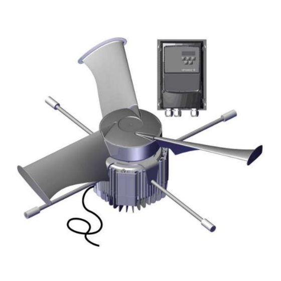
DA 820 LPC -3 1 Product description An LPC (Low Power Consumption) fan is an energy efficient fan unit consisting of a PM (Permanent Magnet) motor with matching motor control and optimized fan blade design for LPC and Dynamic MultiStep systems. -
Page 7: Product Survey
DA 820 LPC -3 2 Product survey 2.1 DA 820 LPC -3 445126 DA 820 LPC 10-3 fan 230V1 50/60Hz 445128 DA 820 LPC 12-3 fan 230V1 50/60Hz The motor controller is to receive a 10-0 V signal. The fan comes with a 2-meter cable for the wiring between motor and motor controller. -
Page 8: Lpc Accessories
DA 820 LPC -3 445136 DA 820 LPC 10-3 fan 230V1 50/60Hz TH The fan is the same as part no. 445126, but includes a thermal cutout. 445139 DA 820 LPC 12-3 fan 230V1 50/60Hz TH The fan is the same as part no. 445129, but includes a thermal cutout. -
Page 9: Mounting Guide
DA 820 LPC -3 3 Mounting guide 3.1 Recommended tools A list of the recommended tools for mounting purposes can be seen below. Item Description Cordless drill Screwdriver bits Drill kit Multimeter Utility knife Cable clip pliers Side cutter Pointed pliers... -
Page 10: Positioning Of Fan In The Exhaust Unit
DA 820 LPC -3 3.2 Positioning of fan in the exhaust unit The connection box on the fan must face downwards when the fan is used as a wall exhaustion. Mount the four fan suspensions using 6 x 25 screws in the marked positions. -
Page 11: Position Of Motor Controller
DA 820 LPC -3 3.4 Position of motor controller Motor controller must not be built-in or covered and must be mounted on a solid, level surface. In order to uphold protection classifications, access and cooling, the motor controller must be positioned as shown in section Mounting distances for the motor controller [} 11]. -
Page 12: Installation Guide
4.1.3 Overvoltage protection SKOV A/S equipment are protected for high level of surge transient, but in some cases, specially in areas with frequent lightning strikes and power outage, additional protection is necessary. To reduce the risk of damaging the electronic equipment by large surge overvoltage, it is therefore recommended, always to install Surge Pro- tection Devices (SPD) in the mains supply. -
Page 13: Cabling In The Exhaust Unit
DA 820 LPC -3 4.1.4 Cabling in the exhaust unit Drill a hole in the exhaust unit duct for the fan cable and lay it along a support to the same side as the motor con- troller. 4.1.5 Cabling into the motor controller... -
Page 14: Connection In The Lpc Motor Controller
DA 820 LPC -3 4.2 Connection in the LPC motor controller Supply terminals one-phase (L1/L, L2/N). Three-phase (L1/L, L2/N, L3) Screw for ground wire Motor connection terminals (U, W, V) Screw for ground wire Shield connection to fan cable Signal terminals... -
Page 15: Terminals For One-Phase Supply
DA 820 LPC -3 4.2.1 Terminals for one-phase supply Supply one-phase. L1/L = phase L2/N = neutral Mount the supplied cable clip on the ground wire and mount it under the ground screw. 4.2.2 Terminals for three-phase supply Supply three-phase. -
Page 16: Signal Terminals
DA 820 LPC -3 4.2.4 Signal terminals *Ground Stop = open Start = GND (Jumper connection between terminal 8 and GND) *Ground (connected to ground screw) Normal = open Reverse = GND (Jumper connection between terminal 15 and GND) *Ground Signal from house controller (factory setting 10-0 V) in case of change, see section 4.4.1... -
Page 17: Led Indication On Display
DA 820 LPC -3 4.3 LED indication on display To display certain warnings, the motor controller has a built-in 6-digit 7-segment LED display. LED segments Display Meaning a, b, c, d, e, f All flashing Overload, the motor output current... - Page 18 DA 820 LPC -3 H 50.0 Motor controller is activated / running, display shows the output frequency [Hz]. A 2.3 Press Navigate. The display will show the motor cur- rent [A]. P 1.50 Press Navigate. The display will show the motor power [kW].
-
Page 19: Change 10-0 V Analog Input Into 0-10 V
DA 820 LPC -3 4.4.1 Change 10-0 V analog input into 0-10 V The factory setting is 10-0 V. StoP Press and hold the Navigate key for more than 2 sec- onds. P-16 Press Up and select P-16 U 10-0 Press Navigate. - Page 20 DA 820 LPC -3 P-16 Press Navigate. The new setting is now saved. StoP Press and hold the Navigate key for more than 2 sec- onds to return to operating mode. Technical User Guide...
-
Page 21: Adjusting The Jumper And Connection In The Winch Motor
DA 820 LPC -3 4.5 Adjusting the jumper and connection in the winch motor Set the jumper on the PCB to give actuator the desired function. LED indication OK = slow flashing Error = quick flashing (10 times/second) H1 Actuator controller or +24 V DC supply... -
Page 22: General Information About Circuit Diagrams
DA 820 LPC -3 4.6 General information about circuit diagrams Symbols are pursuant to the IEC/EN 60617 standard. The classification of the symbols ("letter codes") on the symbols is pursuant to the IEC/EN 81346-2 standard. Reference designations are in accordance with IEC/EN 81346-1:2001 structuring principles and reference des- ignations. -
Page 23: Cable Plans And Circuit Diagrams
DA 820 LPC -3 4.7 Cable plans and circuit diagrams 4.7.1 Circuit diagrams for OFF/AUTO/ON switch 4.7.1.1 Control voltage (LPC with DA 74CO) Example of terminal number For correct connection see the setup menu Show connection in controller Winch motor... -
Page 24: Control Voltage (Lpc With Da 74Cv)
DA 820 LPC -3 4.7.1.2 Control voltage (LPC with DA 74CV) Example of terminal number For correct connection see the setup menu Show connection in controller Winch motor stepless Technical User Guide... -
Page 25: 820 Lpc -3
DA 820 LPC -3 4.7.2 DA 820 LPC -3 4.7.2.1 Cable plan 4.7.2.2 Terminals in LPC 230 V fan Technical User Guide... -
Page 26: Circuit Diagram
DA 820 LPC -3 4.7.2.3 Circuit diagram Example of terminal number For correct connection see the setup menu Show connection in controller LPC motor controller LPC fan Technical User Guide... -
Page 27: 820 Lpc -3 230 V With Da 74Co On/Off
DA 820 LPC -3 4.7.3 DA 820 LPC -3 230 V with DA 74CO ON/OFF 4.7.3.1 Cable plan 4.7.3.2 Terminals in LPC 230 V fan Technical User Guide... -
Page 28: Terminals In Da 74Co
DA 820 LPC -3 4.7.3.3 Terminals in DA 74CO 4.7.3.4 Circuit diagram Power supply from emergency opening 0V = Q1 terminal in controller Power supply from emergency opening 24V-1 = Q2, Q3, Q4 and Q5 terminal in controller. Power supply from emergency opening 24V-12 = F6 terminal in emergency opening. -
Page 29: 820 Lpc -3 230 V With Thermal Cutout And Da 74Co On/Off
DA 820 LPC -3 4.7.4 DA 820 LPC -3 230 V with thermal cutout and DA 74CO ON/OFF 4.7.4.1 Cable plan 4.7.4.2 Terminals in LPC 230 V fan with thermal cutout Technical User Guide... -
Page 30: Terminals In Da 74Co
DA 820 LPC -3 4.7.4.3 Terminals in DA 74CO 4.7.4.4 Circuit diagram Power supply from emergency opening 0V = Q1 terminal in controller Power supply from emergency opening 24V-1 = Q2, Q3, Q4 and Q5 terminal in controller. Power supply from emergency opening 24V-12 = F6 terminal in emergency opening. -
Page 31: 820 Lpc -3 230 V With Da 74Cv Stepless
DA 820 LPC -3 4.7.5 DA 820 LPC -3 230 V with DA 74CV stepless 4.7.5.1 Cable plan 4.7.5.2 Terminals in LPC 230 V fan Technical User Guide... -
Page 32: Terminals In Da 74Cv
DA 820 LPC -3 4.7.5.3 Terminals in DA 74CV 4.7.5.4 Circuit diagram Power supply from emergency opening 0V = Q1 terminal in controller Power supply from emergency opening 24V-1 = Q2, Q3, Q4 and Q5 terminal in controller. Power supply from emergency opening 24V-12 = F6 terminal in emergency opening. -
Page 33: 820 Lpc -3 230 V With Thermal Cutout And Da 74Cv Stepless
DA 820 LPC -3 4.7.6 DA 820 LPC -3 230 V with thermal cutout and DA 74CV stepless 4.7.6.1 Cable plan 4.7.6.2 Terminals in LPC 230 V fan with thermal cutout Technical User Guide... -
Page 34: Terminals In Da 74Cv
DA 820 LPC -3 4.7.6.3 Terminals in DA 74CV 4.7.6.4 Circuit diagram Power supply from emergency opening 0V = Q1 terminal in controller Power supply from emergency opening 24V-1 = Q2, Q3, Q4 and Q5 terminal in controller. Power supply from emergency opening 24V-12 = F6 terminal in emergency opening. -
Page 35: 820 Lpc -3 400 V With Da 74Co On/Off
DA 820 LPC -3 4.7.7 DA 820 LPC -3 400 V with DA 74CO ON/OFF 4.7.7.1 Cable plan 4.7.7.2 Terminals in LPC 400 V fan Technical User Guide... -
Page 36: Terminals In Da 74Co
DA 820 LPC -3 4.7.7.3 Terminals in DA 74CO 4.7.7.4 Circuit diagram Power supply from emergency opening 0V = Q1 terminal in controller Power supply from emergency opening 24V-1 = Q2, Q3, Q4 and Q5 terminal in controller. Power supply from emergency opening 24V-12 = F6 terminal in emergency opening. -
Page 37: 820 Lpc -3 400 V With Da 74Cv Stepless
DA 820 LPC -3 4.7.8 DA 820 LPC -3 400 V with DA 74CV stepless 4.7.8.1 Cable plan 4.7.8.2 Terminals in LPC 400 V fan Technical User Guide... -
Page 38: Terminals In Da 74Cv
DA 820 LPC -3 4.7.8.3 Terminals in DA 74CV 4.7.8.4 Circuit diagram Power supply from emergency opening 0V = Q1 terminal in controller Power supply from emergency opening 24V-1 = Q2, Q3, Q4 and Q5 terminal in controller. Power supply from emergency opening 24V-12 = F6 terminal in emergency opening. -
Page 39: 820 Lpc -3/Da 74Cv Stepless With Reverse
DA 820 LPC -3 4.7.9 DA 820 LPC -3/DA 74CV stepless with reverse 4.7.9.1 Cable plan Technical User Guide... -
Page 40: Circuit Diagram
DA 820 LPC -3 4.7.9.2 Circuit diagram Power supply from emergency opening 0V = Q1 terminal in controller Power supply from emergency opening 24V-1 = Q2, Q3, Q4 and Q5 terminal in controller. Power supply from emergency opening 24V-12 = F6 terminal in emergency opening. -
Page 41: 820 Lpc/Da 74Cv Stepless With Alarm Relay
DA 820 LPC -3 4.7.10 DA 820 LPC/DA 74CV stepless with alarm relay 4.7.10.1 Cable plan Technical User Guide... -
Page 42: Circuit Diagram
DA 820 LPC -3 4.7.10.2 Circuit diagram Power supply from emergency opening 0V = Q1 terminal in controller Power supply from emergency opening 24V-1 = Q2, Q3, Q4 and Q5 terminal in controller. Power supply from emergency opening 24V-12 = F6 terminal in emergency opening. -
Page 43: Maintenance Instructions
When washing the inside of the ducts, fan blades must stand still. Remember that fans do not stand high-pressure cleaning. If the inside of the duct needs to be cleaned extra thoroughly SKOV A/S recommends washing from above. When washing the fan, the fan blades must turn around. -
Page 44: Trouble Shooting Instructions
DA 820 LPC -3 6 Trouble shooting instructions Remember to shut the fan off at the power supply isolator prior to troubleshooting. Wait 10 minutes for the capacitors to discharge to a safe voltage level before servicing and trou- bleshooting. - Page 45 Defective thermistor on the Motor controller defective. Replace motor controller. eat sink. dAtA-F Internal memory error (IO). Press the stop key. Contact SKOV A/S Fan-F Cooling fan error (IP66 Motor controller defective. Replace motor controller. only). O-hEAt Internal temperature of mo- Check that the ambient temperature and distance re- tor controller too high.
-
Page 46: Resetting Errors
DA 820 LPC -3 6.1 Resetting errors When the motor controller stops and an error message is displayed, it can be reset in one of the following ways: • Disconnect the supply voltage for 10 minutes. Reconnect the supply voltage. -
Page 47: Technical Data
DA 820 LPC -3 7 Technical data 7.1 DA 820 LPC -3 1x230 V 445126/445136 445128/445139 DA 820 LPC-10-3 DA 820 LPC-12-3 Electrical V AC 230 ± 10 % Rated voltage V AC 180 – 253 Operating voltage For supply voltages below the rated voltage range, a reduction of the fan’s RPM may occur depending on the load and ambient tempera-... - Page 48 DA 820 LPC -3 445126/445136 445128/445139 DA 820 LPC-10-3 DA 820 LPC-12-3 23600 28200 Air output at -10 Pa 22800 27600 Air output at -20 Pa 21900 27000 Air output at -30 Pa 21000 26200 Air output at -40 Pa...
-
Page 49: Erp/Ecodesign Da 820 Lpc -3 1X230 V
Pressure conditions Recycling/Disposal The product is designed to be recycled and customers will be able to de- liver their used products to SKOV A/S or their local collection points/recy- cling centers in accordance with local instructions. Environmental impact Components used for Bell mouth, flap, air direction baffle, 0.75 m DA 820 duct and outlet cone. -
Page 50: 820 Lpc -3 3X400 V
DA 820 LPC -3 7.2 DA 820 LPC -3 3x400 V 445127 DA 820 LPC 10-3 445129 DA 820 LPC 12-3 3x400 V 3x400 V Electrical V AC 3x400 +/- 10% Rated voltage V AC 360 – 440 Operating voltage For supply voltages below the rated voltage range, a reduction of the fan’s RPM may occur depending on the load and ambient... - Page 51 DA 820 LPC -3 445127 DA 820 LPC 10-3 445129 DA 820 LPC 12-3 3x400 V 3x400 V 19500 24300 Air output at -60 Pa 18500 23500 Air output at 70 Pa 17300 22900 Air output at -80 Pa 16100...
-
Page 52: Erp/Ecodesign Da 820 Lpc -3 3X400 V
DA 820 LPC -3 7.2.1 Erp/Ecodesign DA 820 LPC -3 3x400 V Fan type DA 820 LPC 10-3 DA 820 LPC 12-3 3x400 V 3x400 V ErP 2015 (N58) Ecodesign 81.2 79.3 Efficiency classification 74.4 73.6 Efficiency (η) Measurement setup... -
Page 53: Dimensioned Sketch
DA 820 LPC -3 7.3 Dimensioned sketch 7.3.1 DA 820 LPC -3 LPC motor controller 148.5 LPC fan Technical User Guide... - Page 56 SKOV A/S • Hedelund 4 • Glyngøre • DK-7870 Roslev Tel. +45 72 17 55 55 • www.skov.com • E-mail: skov@skov.dk...
Need help?
Do you have a question about the DA 820 LPC -3 and is the answer not in the manual?
Questions and answers