Table of Contents
Advertisement
Quick Links
Advertisement
Table of Contents

Related Manuals for Skov DA 800 LPC


Summary of Contents for Skov DA 800 LPC
- Page 1 DA 800 LPC Technical User Guide English: For other language variants of this document we refer to: Español: Para otras variantes del idioma de este documento, visite: Français: Pour les versions dans d'autres langues de ce document veuillez consulter: http://docs.skov.com/1052...
- Page 3 Product and Documentation Changes SKOV A/S reserves the right to change this manual and the product described herein without further notice. In case of doubt, please contact SKOV A/S. The date of change appears on the front and back pages.
-
Page 4: Table Of Contents
Circuit Diagram ............................15 4.3.2.1 DA 800 LPC................................15 Dynamic MultiStep ......................16 4.4.1 Cable chart DA 800 LPC with DA 74CO ON/OFF ................16 4.4.2 Circuit Diagram ON/OFF ........................17 4.4.2.1 DA 800 LPC with DA 74CO ON/OFF ........................17 4.4.3 Cable Chart DA 800 LPC with DA 74CV Stepless ................ - Page 5 LED indications ......................... 26 Technical Data ......................27 ErP/Ecodesign ........................28 Dimensioned Sketch ......................29 8.2.1 Motor Controller ............................. 29 8.2.2 Fan ................................ 29 8.2.2.1 DA 800 LPC 0.75 kW ............................29 8.2.2.2 DA 800 LPC 1 kW ..............................29 DA 800 LPC...
-
Page 6: Product Description
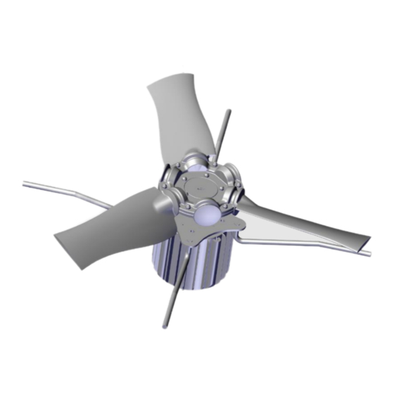
Technical User Guide 1 Product Description DA 800 LPC is an energy-efficient fan which includes a motor control. For LPC (Low Power Consumption) and Dynamic MultiStep systems. The fan is designed for mounting in DA 800 exhaust units in houses where ventilation is operated in low- pressure ranges, i.e. -
Page 7: General Information
Technical User Guide 2 General Information Recommended Tools The following or similar tools are required to service the DA 800 LPC. The tools are not supplied by SKOV A/S. Item Description Multimeter Screwdriver set* Allen key kit Side cutting pliers... -
Page 8: Mounting Guide
For air inlets, the motor must be at the bottom and the fan blade at the top. Safety Distance If the distance from the floor to the fan blade is less than 270 cm, a safety net must be mounted in the bell mouth. 270 cm DA 800 LPC... -
Page 9: Mounting The Motor Control
3.3.1. 3.3.2 Ensure access and cooling of Motor Controller In order to ensure access and cooling of the motor controller, the distances to the surroundings of 150 mm must be adhered to. DA 800 LPC... -
Page 10: Positioning Of Motor Controller
Mount the controller on a wooden plate fastened to a rafter on the ceiling or directly on the chimney. Install the controller under the eaves protected from driving rain and in shade protected from direct solar radiation. DA 800 LPC... -
Page 11: Installation Guide
EU standards that are applicable in Europe. The installation of a power supply isolator is required for each motor and power supply to facilitate voltage-free work on the electrical equipment. SKOV A/S does not supply the power supply isolator. -
Page 12: Connection In The Motor Controller
Remember to strip the cable so that the protective shield from the fan can be connected to the motor controller during mounting under the rail. Power supply 3 x 230 V from motor controller to fan motor. DA 800 LPC... -
Page 13: Signal Terminals
Terminals on Relay Module (accessories) Relay module can be purchased as accessories. 445076 Ground Normal = open Reverse = GND (Jumper between terminal 15 and GND) Not in use Alarm NO Max. 30 V DC/24 V AC, 1A Alarm NC DA 800 LPC... -
Page 14: 800 Lpc Fan
Technical User Guide 4.3 DA 800 LPC Fan 4.3.1 Wiring Diagram Climate computer DA 800 LPC shielded LPC fan DA 800 LPC... -
Page 15: Circuit Diagram
Technical User Guide 4.3.2 Circuit Diagram 4.3.2.1 DA 800 LPC Example of terminal number For correct installation see the setup menu on computer Show Installation DA 800 LPC... -
Page 16: Dynamic Multistep
Technical User Guide 4.4 Dynamic MultiStep 4.4.1 Cable chart DA 800 LPC with DA 74CO ON/OFF Climate computer DA 800 LPC DA 74 shielded LPC fan DA 800 LPC... -
Page 17: Circuit Diagram On/Off
Power supply from emergency opening 24V-1 = Q2, Q3, Q4 and Q5 terminal in Computer. Power supply from emergency opening 24V-12 = F6 terminal in emergency opening. 4.4.2.1 DA 800 LPC with DA 74CO ON/OFF Example of terminal number For correct installation... -
Page 18: Cable Chart Da 800 Lpc With Da 74Cv Stepless
Technical User Guide 4.4.3 Cable Chart DA 800 LPC with DA 74CV Stepless Climate computer DA 800 LPC DA 74 shielded LPC fan DA 800 LPC... -
Page 19: Circuit Diagram Stepless
Power supply from emergency opening 24V-1 = Q2, Q3, Q4 and Q5 terminal in Computer. Power supply from emergency opening 24V-12 = F6 terminal in emergency opening. 4.4.4.1 DA 800 LPC with DA 74CV Stepless Example of terminal number For correct installation... -
Page 20: Cable Chart Da 800 Lpc/Da 74Cv With Reverse
Technical User Guide 4.4.5 Cable Chart DA 800 LPC/DA 74CV with Reverse Climate computer Key switch DA 800 LPC DA 74 shielded Reverse LPC fan DA 800 LPC... -
Page 21: Circuit Diagram Da 800 Lpc/Da 74Cv With Reverse
Technical User Guide 4.4.6 Circuit diagram DA 800 LPC/DA 74CV with Reverse Power supply from emergency opening 0V-1 = Q1 terminal in Computer. Power supply from emergency opening 24V-1 = Q2, Q3, Q4 and Q5 terminal in Computer. Power supply from emergency opening 24V-12 = F6 terminal in emergency opening. -
Page 22: Cable Chart Da 800 Lpc/Da 74Cv With Alarm Relay
Technical User Guide 4.4.7 Cable Chart DA 800 LPC/DA 74CV with Alarm Relay Climate computer DA 800 LPC DA 74 shielded Alarm LPC fan DA 800 LPC... -
Page 23: Circuit Diagram Da 800 Lpc/Da 74Cv With Alarm
Technical User Guide 4.4.8 Circuit diagram DA 800 LPC/DA 74CV with Alarm Power supply from emergency opening 0V-1 = Q1 terminal in Computer. Power supply from emergency opening 24V-1 = Q2, Q3, Q4 and Q5 terminal in Computer. Power supply from emergency opening 24V-12 = F6 terminal in emergency opening. -
Page 24: Setting Fan Voltage In House Computer
DOL 34 The control voltage coming from a DOL 34 house computer is 0-10 V, which is why a short-circuit connection must be mounted between terminal 7 and terminal 10 on the signal terminal, see 4.2.3 Signal Terminals DA 800 LPC... -
Page 25: Maintenance Instructions
Clean using a limited amount of water (water spraying), a brush and a cloth. Removal for Recycling/Disposal SKOV A/S products which are suitable for recycling are marked with a pictogram showing a refuse bin that is crossed over. See the picture. -
Page 26: Troubleshooting Guide
• Lights constantly green when manis voltage is connected. • Lights constantly red when at least one critical alarm is active. • Flashes red when at least one non-critical alarm is active. DA 800 LPC... -
Page 27: Technical Data
Technical User Guide 8 Technical Data Ventilatortype 445077 DA 800 LPC 0.75 kW 445078 DA 800 LPC 1 kW Elektrisk Rated voltage [V AC] 230 ± 10 % 230 ± 10 % Operational voltage [V AC] 160 - 280 160 - 280... -
Page 28: Erp/Ecodesign
Specific ratio The product is designed for recycling and it will be possible for customers to deliver Recycling/disposal worn-out product to SKOV A/S or to local collection sites/recycling stations according to local instructions. Impact on environment Komponenter brugt til bestemmelse Bell mouth, shutter, 1 m duct and outlet cone. -
Page 29: Dimensioned Sketch
Technical User Guide Dimensioned Sketch 8.2.1 Motor Controller 8.2.2 8.2.2.1 DA 800 LPC 0.75 kW 8.2.2.2 DA 800 LPC 1 kW DA 800 LPC... - Page 30 DA 800 LPC...
- Page 32 SKOV A/S • Hedelund 4 • Glyngøre • DK-7870 Roslev Tel. +45 72 17 55 55 • Fax +45 72 17 59 59 • www.skov.com • Email: skov@skov.dk...
Need help?
Do you have a question about the DA 800 LPC and is the answer not in the manual?
Questions and answers