Skov DA 1700 Technical User Manual
Wall fan without diffusor and shutter
Hide thumbs
Also See for DA 1700:
- Technical user manual (68 pages) ,
- Technical user manual (112 pages)
Table of Contents
Advertisement
Quick Links
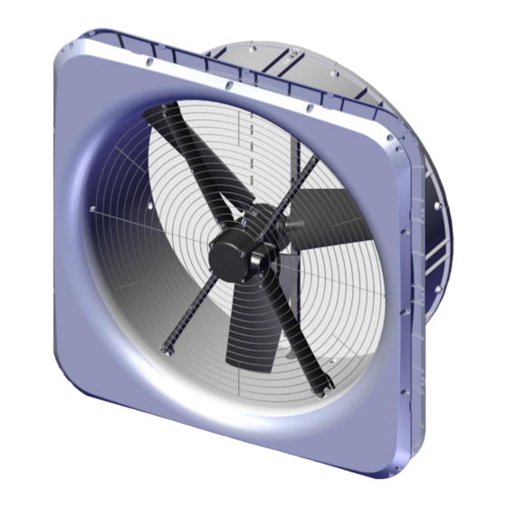
DA 1700 Wall Fan
Without diffusor and shutter
Technical User Guide
English: For other language variants of this document we refer to:
Español: Para otras variantes del idioma de este documento, visite:
Français: Pour les versions dans d'autres langues de ce document veuillez consulter:
http://docs.skov.com/1195
2018.03.06 • S604252A
Advertisement
Table of Contents

Related Manuals for Skov DA 1700


Summary of Contents for Skov DA 1700
- Page 1 DA 1700 Wall Fan Without diffusor and shutter Technical User Guide English: For other language variants of this document we refer to: Español: Para otras variantes del idioma de este documento, visite: Français: Pour les versions dans d'autres langues de ce document veuillez consulter: http://docs.skov.com/1195...
- Page 3 Product and Documentation Changes SKOV A/S reserves the right to change this manual and the product described herein without further notice. In case of doubt, please contact SKOV A/S. The date of change appears on the front and back pages.
-
Page 4: Table Of Contents
Placement in the Livestock House ................. 9 General Drawings ....................9 Preparing Hole in Wall ....................10 4.3.1 Necessary Space for DA 1700 with LPC Motor Controller ..........10 4.3.2 Round Hole in Sandwich Wall ..................11 4.3.3 Measure and Saw Out the Holes ..................12 4.3.4... - Page 5 5.6.2 Power Supply Isolator ...................... 35 5.6.3 Letter Codes ........................35 5.6.4 Cable Plan DA 1700 LPC 3x400 V ..................35 5.6.5 Circuit Diagram DA 1700 LPC 3x400 V ................36 MAINTENANCE INSTRUCTIONS ..............37 Cleaning the Fan .....................37 Cleaning the LPC Motor Controller ...............37 Dismantling for Recycling/Disposal ..............37...
-
Page 6: Product Description
Technical User Guide 1 Product Description The DA 1700 wall fan is a flange-mounted corrosion-free fan with cone DA 1700 is designed especially for the demanding house environment both when it comes to climatic and electrical impacts. 2 Product Survey... - Page 7 Technical User Guide At every order up to 100 pcs. DA 1700 wall fans, 1 pc. DA 1700 lifting kit and extra mounting parts are supplied. At every order from 101-200 pcs., DA 1700 wall fans, 2 pcs. DA 1700 lifting kit and extra mounting parts are supplied.
-
Page 8: General Information
Technical User Guide 3 General Information Recommended Tools Below follows a list of tools recommended for installation of your DA 1700 wall fan. Part Description Cordless drill Jigsaw Socket wrench set, incl. 10 and 17 mm top Combination spanner kit, incl. 10 mm and 17 mm... -
Page 9: Mounting Guide
DA 1700 wall fans are placed in the livestock house according to the drawing supplied. Contact SKOV A/S in case of significant deviation. It is checked that all DA 1700 wall fans can be placed freely in relation to the other equipment, upon agreement with the owner. -
Page 10: Preparing Hole In Wall
Technical User Guide Preparing Hole in Wall 4.3.1 Necessary Space for DA 1700 with LPC Motor Controller There must be a minimum of 125 mm of space inside the livestock house for the DA 1700 wall fan. There must be minimum of... -
Page 11: Round Hole In Sandwich Wall
The minimum distance with use of LPC controller is 550 mm. Without an LPC controller, the distance can be reduced to a minimum of 275 mm. Figure 3: Minimum distance between DA 1700 Figure 4: Minimum distance from DA 1700 to wall, floor and ceiling DA 1700 Wall Fan... -
Page 12: Measure And Saw Out The Holes
Technical User Guide 4.3.3 Measure and Saw Out the Holes Remember to always use a spirit level. The holes should be roughly 10 mm right through the wall. Cut the holes. DA 1700 Wall Fan... -
Page 13: Press The Front Panel Together
Technical User Guide 4.3.4 Press the Front Panel Together Lay the four front panels on the floor. Press the front panels together in all four corners. DA 1700 Wall Fan... -
Page 14: Click And Seal The Ventilation Ducts Together
Technical User Guide 4.3.5 Click and Seal the Ventilation Ducts Together Point the side of the ventilation duct. Click the four ventilation ducts together alternately. entilation ducts without motor suspension (1). entilation ducts with motor suspension (2). DA 1700 Wall Fan... -
Page 15: Position The Ventilation Duct On The Front Panel
Mount the Ventilation Duct on the Front Panel Assemble the front panel and the ventilation duct using: • 16 M6x25 screws • 32 Ø6 washers • 16 bushings ø6/ø10 x 11.6 • 16 M6 self-locking nuts DA 1700 Wall Fan... - Page 16 Technical User Guide Then assemble the front panel and the ventilation Duct using: • 12 M6x25 screws • 24 Ø6 washers • 12 bushings ø6/ø10 x 11.6 • 12 M6 self-locking nuts DA 1700 Wall Fan...
-
Page 17: Mount The Centre Pillar On The Ventilation Duct
Mount the Centre Pillar on the Ventilation duct Mount the Centre pillar on the ventilation duct using: • 4 M6x25 screws • 8 Ø6 washers • 4 bushings ø6/ø10 x 11.6 • 4 M6 self-locking nuts Bottom DA 1700 Wall Fan... -
Page 18: Mount Da 1700 In Wall
Technical User Guide 4.3.9 Mount DA 1700 in Wall Centre DA 1700 in the hole, use wedges at the bottom. Use the holes in DA 1700 to mark out holes in the wall. Drill 3 mm holes in the wall. -
Page 19: Mount Fan Blades On The Motor Shaft
Technical User Guide 4.3.10 Mount Fan Blades on the Motor Shaft For the assembly of fan blades see Instruction included in DA 1700 fan blade kit. The grooves on the fan blade and the grooves on the axle must be in line with each other. -
Page 20: Mount Lifting Kit
4.3.13 Mount Motor to Bottom Motor Suspensions in the Fan Housing Mount motor with the two bottom motor suspensions in the fan housing using: • 2 M6x80 screws • 4 Ø6 washers • 2 bushings ø6/ø10 x 69.6 • 2 M6 self-locking nuts DA 1700 Wall Fan... -
Page 21: Mount Top Motor Suspensions To The Motor And The Fan Housing
Select where cables must come out, in the side or in the bottom, and drill a hole with the aid of centre marks: • 13 mm hole for the fan motor cable at the bottom. DA 1700 Wall Fan... - Page 22 Mount the fan motor cable on the motor suspension using: • 3 cable ties 188 x 4.8 mm, black Pull the cable around the ventilation duct and in through the drilled hole. For sealing when leading through cables, see section 4.3.17. DA 1700 Wall Fan...
-
Page 23: Foam And Seal The Outer Side
Technical User Guide 4.3.16 Foam and Seal the Outer Side Seal the outer side before placing the diffuser on the ventilation duct. Foam around the ventilation duct. Foam in four places around the ventilation duct. DA 1700 Wall Fan... - Page 24 Technical User Guide With use of outside cover, apply a sealing edge at the transition between wall and duct. DA 1700 Wall Fan...
-
Page 25: Seal The Inner Side
Technical User Guide 4.3.17 Seal the Inner Side Apply a sealing edge between the wall fan and the wall. Apply a seal next to the place where the cables have been led through. DA 1700 Wall Fan... -
Page 26: Mounting Of Inside Safety Net
In the two holes in the sides of the fan housing. Secure the inside safety net in the four motor suspension brackets using: • 12 4x30 screws • 12 Ø4.3 washers Ensure the screws are screwed in tightly. DA 1700 Wall Fan... -
Page 27: Mounting Of Accessories
If necessary, use a saw to adjust the cover size. Then mount all four covers on the wall with the aid of screws (not supplied by SKOV A/S) For sealing, see section 4.3.16 DA 1700 Wall Fan... -
Page 28: Installation Guide
EU standards that are applicable in Europe. The installation of a power supply isolator is required for each motor and power supply to facilitate voltage-free work on the electrical equipment. SKOV A/S does not supply the power supply isolator. -
Page 29: Connection In The Lpc Motor Controller
Terminal block for Modbus and A/D control signal RJ12 Modbus connector (2 x slave / 1 x master) 3-point strain relief for Modbus cable Power supply terminals for 1-phase (L, N, PE) and 3-phase (L1, L2, L3, N, PE) DA 1700 Wall Fan... -
Page 30: Terminals For 400 V Power Supply
Terminals for Power Supply to Fan Remember to strip the cable so that the protective shield from the fan can be connected to the motor controller during mounting under the rail. Power supply from motor controller to fan motor. DA 1700 Wall Fan... -
Page 31: Signal Terminals
Signal from climate computer (speed regulation of motor) Ground 10-0 V = open 0-10 V = GND (Jumper between terminal 7 and GND) Stop = open Start = GND (Jumper between terminal 8 and GND) Not in use Ground DA 1700 Wall Fan... -
Page 32: Led Indication On Lpc Motor Controller
• Flashes red in case of at least one non-critical alarm. Alarms DA 1700 LPC motor controller including relay module provides alarm monitoring which monitors the optimal and flawless operation and generates an alarm if operating or performance problems are observed. -
Page 33: Connection To Kick On Timer
D OUT LPC motorstyring ON/OFF Max. 3 LPC controller on 1 Kick ON timer Operating temperature [°C] ÷ 40 to +50 Storage temperature [°C] ÷ 40 to +70 Ambient humidity, operation [%] RH 10 to 95 DA 1700 Wall Fan... -
Page 34: Mounting The Kick On Timer On Din Rail
Technical User Guide 5.5.2 Mounting the Kick ON Timer on DIN Rail DA 1700 Wall Fan... -
Page 35: Cable Plans And Circuit Diagrams
Climate controller Fan motor Supply isolator Switch Cable RCCB Contactor Initial fuse Protective motor switch 5.6.4 Cable Plan DA 1700 LPC 3x400 V Climate computer DA 1700 wall fan DA 1700 controller Connection box Supply Supply isolator 4 m shielded cable... -
Page 36: Circuit Diagram Da 1700 Lpc 3X400 V
Technical User Guide 5.6.5 Circuit Diagram DA 1700 LPC 3x400 V Example of terminal number. For correct installation see the setup menu on computer Show connection Power supply from terminals in the climate computer DA 1700 Wall Fan... -
Page 37: Maintenance Instructions
Clean using a limited amount of water (water spraying), a brush and a cloth. Dismantling for Recycling/Disposal SKOV A/S products which are suitable for recycling are marked with a pictogram showing a refuse bin that is crossed over. See the picture. -
Page 38: Troubleshooting Guide
Motor protection switches off Check whether the fan motor is blocked. Remove the blocking. Fan motor is not Too high negative pressure in the running. livestock house, check the air inlets. LPC motor: See Troubleshooting LPC motor controller DA 1700 Wall Fan... - Page 39 Start/stop signal (24V = stop terminal Fan motor is not Check signal from the winch motor. running Supply is lacking. Check supply. No light Defective LPC motor controller. Replace LPC motor controller. * For LED indications, see section 5.3 DA 1700 Wall Fan...
-
Page 40: Technical Data
Technical User Guide 8 Technical data DA 1700 LPC 3x400 V 435308 Electrical DA 1700-6 LPC 3x400 V 3x400 ± 10 % Rated voltage [V AC] 280 - 485 Operational voltage [V AC] To be installed in accordance with applicable laws and standards. -
Page 41: Erp/Ecodesign Da 1700 Lpc 3X400 V
Specific ratio Recycling/Disposal The product is designed for recycling and it will be possible for customers to deliver worn-out product to SKOV A/S or to local collection sites/recycling stations according to local instructions. Impact on environmental Additional items used when determining the fan energy DA 1700 wall fan incl. -
Page 42: Dimensioned Sketch
Technical User Guide Dimensioned Sketch Measure in mm. 8.4.1 DA 1700 LPC with Motor Controller 8.4.2 Motor Controller LPC 3x400V DA 1700 Wall Fan... -
Page 43: Enclosures
Assembly Foaming Pointing Check that all joints are in accordance with Technical User Guide DA 1700 wall fan. Check that the setting of the motor protection is correct, see section 8 Technical data (Max. power consumption [A]). Make sure that there is no contactor in front of the fan with LPC motor controller. - Page 44 SKOV A/S • Hedelund 4 • Glyngøre • DK-7870 Roslev Tel. +45 72 17 55 55 • Fax +45 72 17 59 59 • www.skov.com • Email: skov@skov.dk...
Need help?
Do you have a question about the DA 1700 and is the answer not in the manual?
Questions and answers