Skov DA 1700 Technical User Manual
With dual actuator
Hide thumbs
Also See for DA 1700:
- Technical user manual (112 pages) ,
- Technical user manual (44 pages)
Table of Contents
Advertisement
Quick Links
DA 1700 dual actuator
Wall Fan
Technical User Guide
English For other language variants of this document we refer to:
Español Para otras variantes del idioma de este documento, visite:
Français Pour les versions dans d'autres langues de ce document veuillez consulter:
http://docs.skov.com/1195
604420 • 2021-08-17
Advertisement
Table of Contents

Subscribe to Our Youtube Channel
Related Manuals for Skov DA 1700


Summary of Contents for Skov DA 1700
- Page 1 DA 1700 dual actuator Wall Fan Technical User Guide English For other language variants of this document we refer to: Español Para otras variantes del idioma de este documento, visite: Français Pour les versions dans d'autres langues de ce document veuillez consulter: http://docs.skov.com/1195...
- Page 2 The date of change appears from the front and back pages. Note • All rights belong to SKOV A/S. No part of this manual may be reproduced in any manner whatsoever without the expressed written permission of SKOV A/S in each case.
-
Page 3: Table Of Contents
DA 1700 dual actuator 1 Product description............................ 5 2 Product survey ............................... 6 DA 1700 wall fan ........................ 6 Accessories.......................... 7 3 Mounting guide............................. 10 Recommended tools........................ 10 Placement of wall fan ...................... 12 Preparing hole in wall...................... 12 3.3.1 Necessary space for wall fan without LPC motor controller............ 12 3.3.2... - Page 4 6 Troubleshooting instructions........................ 58 7 Technical data............................... 60 DA 1700-6 LPC ACT 3x400 V .................... 60 7.1.1 ErP/Ecodesign DA 1700-6 LPC ACT 3x400 V ................ 62 DA 1700-7 ACT 3x400 V...................... 63 7.2.1 ErP/Ecodesign DA 1700-7 ACT 3x400 V .................. 64 Actuator ............................ 65 8 Dimensioned sketch............................. 66...
-
Page 5: Product Description
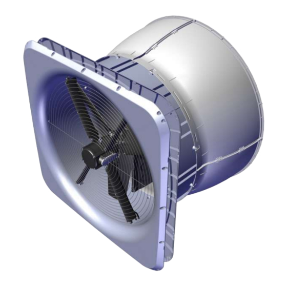
DA 1700 dual actuator is characterized by having a particularly tightly closed shutter, which prevents unwanted air movement when the fan is not in operation, and a direct-driven motor to reduce motor maintenance. DA 1700 dual actuator is specially designed for harsh livestock house environments. This applies to both cli- matic and electrical influences. -
Page 6: Product Survey
2.1 DA 1700 wall fan For every 100 pcs. DA 1700 wall fans, 1 pcs. DA 1700 lifting kit and mounting parts are supplied. For every 101-200 pcs., 2 pcs. DA 1700 lifting kit and mounting parts, etc. are supplied. -
Page 7: Accessories
If a DA 1700 outside safety net is deselected: • A safety guard must be established. • The 435337 DA 1700 storm protection wire for cone must be bought separately. • The requirements of the International Standard for Safety of machinery ISO 13857 must be complied with. - Page 8 DA 1700 dual actuator 435337 DA 1700 storm protection wire for cone The DA 1700 storm protection wire for cone is used, if the DA 1700 outside safety net is deselected. 1 per wall fan. 435375 DA 1700 outside suspension Used if required if DA 1700 is sagging and has not maintained its round- ness.
- Page 9 435325 DA 1700 light trap black out The light trap is mounted and removed manually. Supplied as an unassembled unit incl. brackets. Used for DA 1700 wall fan if a large amount of dimming is required in the livestock house. Light reduction factor 11.000.000:1.
-
Page 10: Mounting Guide
Check that the parts ordered are present and undamaged before starting work. Please read through the entire guide before starting assembly and fitting. If the DA 1700 is installed in areas with risk of ice/snow slide, precautions must be made to avoid damage to the wall fan. - Page 11 DA 1700 dual actuator Item Description Foam gun Ladder Jigsaw Socket wrench set Water pump (multi-grip) pliers Spirit level Try square 2 men Technical User Guide...
-
Page 12: Placement Of Wall Fan
DA 1700 dual actuator 3.2 Placement of wall fan The wall fan must be placed in the livestock house according to the drawing supplied. Contact SKOV A/S in case of significant deviation. Check that all wall fans can be placed freely in relation to other housing equipment upon agreement with the client. -
Page 13: Measurements For Round Hole In Sandwich Wall
DA 1700 dual actuator 3.3.3 Measurements for round hole in sandwich wall The dimensions below are given in mm . Recommended measurements for individual mounting of wall fan. (A) Minimum distance is 550 mm, when mounting the LPC motor controller above wall fan. Without LPC motor controller, the distance can be reduced to a minimum of 275 mm. -
Page 14: Measurements For Square Hole In Concrete And Brick Wall
DA 1700 dual actuator 3.3.4 Measurements for square hole in concrete and brick wall The dimensions below are given in mm . Recommended measurements for individual mounting of wall fan. (A) Minimum distance is 550 mm, when mounting the LPC motor controller above wall fan. Without LPC motor controller, the distance can be reduced to a minimum of 275 mm. -
Page 15: Measurements For Square Hole In Wooden Wall
DA 1700 dual actuator 3.3.5 Measurements for square hole in wooden wall The dimensions below are given in mm . Recommended measurements for individual mounting of wall fan. (A) Minimum distance is 550 mm, when mounting the LPC motor controller above wall fan. Without LPC motor controller, the distance can be reduced to a minimum of 275 mm. -
Page 16: Measure And Saw Out The Holes
DA 1700 dual actuator 3.4 Measure and saw out the holes Remember always to use a spirit level. Drill 10 mm holes all the way through the wall. Cut the holes. Technical User Guide... -
Page 17: Press The Front Panel Together
DA 1700 dual actuator 3.5 Press the front panel together Lay the 4 front panels on the floor. Press the front panels together in all 4 corners. 3.6 Click and point the ventilation ducts together Point the side of the ventilation duct. -
Page 18: Mounting Ventilation Duct On Front Panel
DA 1700 dual actuator 3.7 Mounting ventilation duct on front panel Position the ventilation duct on the front panel. Assemble the front panel and the ventilation duct using: • 16 x M6x25 screws • 32 x ø6 washers • 16 x bushings ø6/ø10x11.6 •... -
Page 19: Mounting Center Pillar
DA 1700 dual actuator 3.8 Mounting center pillar Mount the two shutters, one at a time, in the center pillar. Mount top and bottom brackets on the center pillar using: • 2 x M6x50 screw • 4 x ø6.4/ø18x1.2 washers •... - Page 20 DA 1700 dual actuator Mount the shutter lock through the shutter and down around the center pillar. Make sure that the shutter lock snaps into the center pillar. Technical User Guide...
-
Page 21: Mounting Actuator
DA 1700 dual actuator 3.9 Mounting actuator Place the dual actuator bracket for center pillar on the center pillar. Mount the dual actuator bracket for center pillar on the center pillar using: • 2 x M6x60 screw • 4 x ø6.4/ø18x1.2 ø18 washers •... - Page 22 DA 1700 dual actuator Mount the actuator on the dual actuator bracket for cen- ter pillar using: • 2 x M6x30 screw • 4 x ø6.4/ø18x1.2 ø18 washers • 2 x ø6/ 10x22 bushings • 2 x M6 self-locking nut...
-
Page 23: Mounting In Wall
DA 1700 dual actuator 3.10 Mounting in wall Center the wall fan in the hole, use wedges at the bot- tom. Use the holes in the wall wall to mark out holes in the wall. Mounting in a sandwich wall: Drill 3 mm holes in the wall. -
Page 24: Mounting Impeller
DA 1700 dual actuator 3.11 Mounting impeller For the assembly of fan blades see Mounting guide DA 1700 impeller. The 3 blades delivered together must NOT be mixed with other blades. The grooves on the fan blade and the grooves on the axle must be in line with each other. -
Page 25: Mounting Lifting Kit
DA 1700 dual actuator 3.13 Mounting lifting kit Mount the lifting kit on the ventilation duct using: • 2 x M6x80 screw • 4 x ø6 washers • 2 x bushings ø6/ø10x69.6 Make sure the blades do not touch the floor. -
Page 26: Mounting The Motor In The Fan Housing
DA 1700 dual actuator 3.14 Mounting the motor in the fan housing Mount motor with the two bottom motor suspensions in the fan housing using: • 2 x M6x80 screws • 4 x ø6 washers • 2 x bushings ø6/ø10x69.6 •... -
Page 27: Cabling From Motor And Actuator
DA 1700 dual actuator 3.16 Cabling from motor and actuator (A) Drill a 10 mm hole for actuator cables at centre mark. (B) Drill a 13 mm hole for actuator cables at centre mark. (C) Select where to exit the cables at the side or at the bottom and drill a hole at centre mark: •... -
Page 28: Foaming And Pointing Of The Outside
DA 1700 dual actuator 3.17 Foaming and pointing of the outside SKOV A/S recommends: • For foaming Single-component polyurethane foam or similar. Check how much the foam ex- pands before foaming. • For pointing Sikaflex 111 Stick & Seal. At round holes foam around the ventilation duct. -
Page 29: Pointing Of The Inside
DA 1700 dual actuator 3.18 Pointing of the inside SKOV A/S recommends Sikaflex 111 Stick & Seal. Apply a sealing edge between the wall fan and the wall. Apply a sealing next to all places where the cables have been led through. -
Page 30: Mounting Of Wall Cover Outside
If necessary, use a saw to adjust the cover size. Then mount all 4 covers on the wall with the aid of screws (not supplied by SKOV A/S). For sealing, see the section Foaming and pointing of the outside [} 28]... -
Page 31: Mounting The Cone
DA 1700 dual actuator 3.20 Mounting the cone Ensure the tongue and groove at the base are in line. Click the sides together. Mount the assembled cone onto the ventilation duct us- ing: • 8 x M6x25 screws • 16 x ø6 washers •... -
Page 32: Mounting Of Inside Safety Net
DA 1700 dual actuator 3.21 Mounting of inside safety net Mount the inside safety net using: • 2 x 4x30 screw • 2 x ø4.3 washers • 2 x mounting straps for inside net in the 2 holes in the fan housing sides. -
Page 33: Mounting Of Accessories
3.22 Mounting of accessories 3.22.1 Mounting of outside safety net If a DA 1700 outside safety net has not been selected, a safety guard must be established. The requirements of the International Standard for Safety of machinery ISO 13857 shall be complied with. -
Page 34: Mounting Storm Protection On Outside Safety Net
DA 1700 dual actuator 3.22.2 Mounting storm protection on outside safety net Mount the storm protection on the outside safety net us- ing: • 2 x PT screws 6x20 torx 30 Make sure that the flaps can open and close when the storm protection is mounted. -
Page 35: Mounting Outside Suspension
DA 1700 dual actuator 3.22.4 Mounting outside suspension Mount the pulley on the wall using (A) screws for con- crete, wall and iron or (B) threaded rod for sandwich panel. Screws for mounting are not included. (C) Mount mounting fittings on ventilation duct with screw and washer for center pillar. -
Page 36: Mounting Support Kit
DA 1700 dual actuator 3.22.5 Mounting support kit Mount wall fitting (A) on ventilation duct using: • 1 x 6x50 screws • 2 x ø6.4/ø18x1.2 washers • 1 x ø6/ø10x11.6 bushings • 1 x M6 self-locking nut Mount threaded rod (B) in bracket (A). -
Page 37: Mounting Insulation Plate
DA 1700 dual actuator 3.22.6 Mounting insulation plate Mount the lock on the motor using: • 1 x 8x12 screw with inside hexagon • 1 x ø8.4 washers Mount the insulation cover at the end of the fan motor using:... -
Page 38: Installation Guide
4.1.1 Disclaimer at retrofitting fans In the case of retrofitting fans in an existing house, regardless of ON/OFF or LPC fans, SKOV recommends that a local expert is involved in checking the electrical installations. The focus should be on cable dimensions, over- load protections, local transformers, etc. -
Page 39: Cabeling And Placement Of Lpc Motor Controller
DA 1700 dual actuator 4.1.4 Cabeling and placement of LPC motor controller Motor controller must not be built-in or covered and must be mounted on a solid, level surface. In order to uphold protection classifications, ensure ac- cess of cables and cooling of the motor controller, the distances to the surroundings of 150 mm must be ad- hered to. -
Page 40: Connection In The Lpc Motor Controller
DA 1700 dual actuator 4.2 Connection in the LPC motor controller Motor connection terminals (U, V, W, PE) Connection terminals for braking resistor (not used) Connector for optional module Terminal block for programming interface RJ12 programming connector (2 x slave / 1 x master) -
Page 41: Terminals For Power Supply
DA 1700 dual actuator 4.2.1 Terminals for power supply Power supply 3 x 400 V / 3 x 230 V. Power supply 1 x 230 V. Technical User Guide... -
Page 42: Terminals For Power Supply Of Fan
DA 1700 dual actuator 4.2.2 Terminals for power supply of fan Remember to strip the cable so that the protective shield from the fan can be connected to the motor controller during mounting under the rail. Connection from motor controller to fan motor. -
Page 43: Led Indication On The Motor Controller
DA 1700 dual actuator 4.3 LED indication on the motor controller The motor controller is equipped with a two-color LED for indication of different operating modes. LED is located on the underside next to the cable glands. • Constantly green when mains voltage is connected. -
Page 44: Emergency Opening For Shutter Motor
DA 1700 dual actuator 4.5 Emergency opening for shutter motor If emergency opening of actuator/shutter motor is required, the actuator/shutter motor must be powered by an F6 24V power supply in the controller. For fans that do not require emergency opening, the actuator/shutter motor is powered by an external 24V power supply without battery backup. -
Page 45: Fan Not Active At Power Failure
DA 1700 dual actuator 4.5.2 Fan not active at power failure To deactivate the fan at a power failure, select | Installation | Manual installation | cli- mate | Air outlet | Tunnel outlet and after that Fans active at failure in the controller menu. -
Page 46: Connection To Actuator
DA 1700 dual actuator 4.6 Connection to actuator LPC control signal. Open / Closed LPC motor controller ON/OFF motor controller Actuator extending (open) 12 sec. 12 sec. retracting (closed) Open/close delay 15 sec. 4 sec. ON/OFF control signal. Open / Closed... -
Page 47: Connection Of Extra 24 V Power Supply
DA 1700 dual actuator 4.7 Connection of extra 24 V power supply Internal power supply (A) may only be used to supply factory-installed modules. In case of a greater power consumption than 0.4 A from the main module (B) and 0.4 A from the I/O modules (C) an extra power supply (D) must be used and possibly (E). -
Page 48: Jumper Setting
DA 1700 dual actuator 4.8 Jumper setting LPC fan mode 1 mode 6 ON/OFF fan mode 0 mode 6 Technical User Guide... -
Page 49: General Information About Circuit Diagrams
DA 1700 dual actuator 4.9 General information about circuit diagrams Symbols are pursuant to the IEC/EN 60617 standard. The classification of the symbols ("letter codes") on the symbols is pursuant to the IEC/EN 81346-2 standard. Reference designations are in accordance with IEC/EN 81346-1:2001 structuring principles and reference des- ignations. -
Page 50: Cable Plans And Circuit Diagrams
DA 1700 dual actuator 4.10 Cable Plans and Circuit Diagrams 4.10.1 Circuit diagram for OFF/AUTO/ON switch 4.10.1.1 DA 1700 with LPC Example of terminal number For correct connection see the setup menu Show connections in the controller Power supply from terminals... -
Page 51: 1700 On/Off
DA 1700 dual actuator 4.10.1.2 DA 1700 ON/OFF Example of terminal number For correct connection see the setup menu Show connections in the controller Power supply from terminals in the climate computer Connection Actuator pcb Dual actuator ! Pay attention to the current consumption of the actuator, see section 7.3... -
Page 52: 1700 Lpc With Alarm Relay
DA 1700 dual actuator 4.10.2 DA 1700 LPC with alarm relay 4.10.2.1 Cable plan DA 1700 dual actuator Controller LPC motor controller Alarm Connection Power supply isolator 4.10.2.2 Circuit diagram Example of terminal number For correct connection see the setup menu... -
Page 53: 1700 Lpc 3X400 V
DA 1700 dual actuator 4.10.3 DA 1700 LPC 3x400 V 4.10.3.1 Cable plan DA 1700 dual actuator Controller LPC motor controller Connection box Power supply isolator 4.10.3.2 Terminals in LPC 3 x 400 V fan Internal External Technical User Guide... -
Page 54: Dual Actuator Control Box Lpc
DA 1700 dual actuator 4.10.3.3 Dual actuator control box LPC 4.10.3.4 Circuit diagram Example of terminal number For correct connection see the setup menu Show connections in the controller Power supply from terminals in the climate computer Connection box Actuator pcb... -
Page 55: 1700 On/Off 3X400 V
DA 1700 dual actuator 4.10.4 DA 1700 ON/OFF 3x400 V 4.10.4.1 Cable plan Controller DA 1700 dual actuator ON/OFF Wiring box Power supply isolator Connection box 4.10.4.2 Terminals in ON/OFF 3 x 400 V fan Internal External Technical User Guide... -
Page 56: Dual Actuator Control Box On/ Off
DA 1700 dual actuator 4.10.4.3 Dual actuator control box ON/ OFF 4.10.4.4 Circuit diagram Example of terminal number For correct connection see the setup menu Show connections in the controller Power supply from terminals in the climate computer Connection Actuator pcb... -
Page 57: Maintenance Instructions
When washing the inside of the ducts, fan blades must stand still. Remember that fans do not stand high-pressure cleaning. If the inside of the duct needs to be cleaned extra thoroughly SKOV A/S recommends washing from above. When washing the fan, the fan blades must turn around. -
Page 58: Troubleshooting Instructions
DA 1700 dual actuator 6 Troubleshooting instructions Remember to shut the fan off at the power supply isolator prior to troubleshooting. Troubleshooting flap system Fault symptom Status LED Error Solution Flap touches the ventilation Remedy the damage. duct (obstructed). Quick flash Actuator blocked. - Page 59 DA 1700 dual actuator Troubleshooting fan motor Fault symptom Status LED Error Solution See Troubleshooting LPC mo- tor controller Fan motor running and AC motor: Check 24 V DC supply voltage. does not turn off. 24 V DC supply to the winch motor is lacking.
-
Page 60: Technical Data
DA 1700 dual actuator 7 Technical data 7.1 DA 1700-6 LPC ACT 3x400 V 435369 DA 1700-6 LPC ACT 3x400 V Electrical V AC 3x400 ± 10% Rated voltage V AC 280 – 485 Operating voltage For supply voltages below the rated voltage range, a reduction of the fan’s RPM may occur depending on the load and ambient... - Page 61 DA 1700 dual actuator 435369 DA 1700-6 LPC ACT 3x400 V pcs. Number of fan blades ° Fan blade pitch Fan output Revolutions per minute 65800 Air output at 0 Pa 63600 Air output at -10 Pa 61700 Air output at -20 Pa...
-
Page 62: Erp/Ecodesign Da 1700-6 Lpc Act 3X400 V
DA 1700 dual actuator 7.1.1 ErP/Ecodesign DA 1700-6 LPC ACT 3x400 V Fan type DA 1700-6 LPC ACT 3x400 V ErP 2015 (40) Ecodesign 61.7 Efficiency classification 57.7 Efficiency (η) Measurement setup Static Fan efficiency 36.0 Optimum efficiency VSD required... - Page 63 DA 1700 dual actuator 7.2 DA 1700-7 ACT 3x400 V 435370 DA 1700-7 ACT 3x400 V Electrical V AC 400 +/-10% Rated voltage V AC 360 – 440 Operating voltage Frequency Max. current consump- tion At 400 V AC supply 2260 Max.
- Page 64 Fan housing weight 6784 Cover 2600 Inside safety net weight 34800 Fan motor weight 7500 Impeller weight 7.2.1 ErP/Ecodesign DA 1700-7 ACT 3x400 V Fan type DA 1700-7 ACT 3x400 V ErP 2015 (40) Ecodesign 53.2 Efficiency classification 49.1 Efficiency (η)
-
Page 65: Actuator
DA 1700 dual actuator 7.3 Actuator Actuator Electrical V DC Rated voltage V DC 14 - 28 Operating voltage Max. current consump- tion at 24 V DC power supply Max. idle current pcs. Number of actuators on a SKOV power supply 24V 2.1/4.2A*... -
Page 66: Dimensioned Sketch
DA 1700 dual actuator 8 Dimensioned sketch 8.1 Wall fan with LPC motor controller DA 1700 with LPC motor controller 8.2 Wall fan DA 1700 without LPC motor controller Technical User Guide... -
Page 67: Lpc Motor Controller
DA 1700 dual actuator 8.3 LPC motor controller LPC motor controller 3x400 V 8.4 Light trap Light trap black/brown out Technical User Guide... - Page 68 SKOV A/S • Hedelund 4 • Glyngøre • DK-7870 Roslev Tel. +45 72 17 55 55 • www.skov.com • E-mail: skov@skov.dk...
Need help?
Do you have a question about the DA 1700 and is the answer not in the manual?
Questions and answers