Skov BF 50 Recirculation Technical User Manual
Hide thumbs
Also See for BF 50 Recirculation:
- Technical user manual (124 pages) ,
- Technical user manual (40 pages)
Table of Contents
Advertisement
Quick Links
BF 50 Recirculation
Technical User Guide
English For other language variants of this document we refer to:
Español Para otras variantes del idioma de este documento, visite:
Français Pour les versions dans d'autres langues de ce document veuillez consulter:
http://docs.skov.com/1241
604435 • 2023-01-24
Advertisement
Table of Contents

Related Manuals for Skov BF 50 Recirculation


Summary of Contents for Skov BF 50 Recirculation
- Page 1 BF 50 Recirculation Technical User Guide English For other language variants of this document we refer to: Español Para otras variantes del idioma de este documento, visite: Français Pour les versions dans d'autres langues de ce document veuillez consulter: http://docs.skov.com/1241...
- Page 3 Note • All rights belong to SKOV A/S. No part of this manual may be reproduced in any manner whatsoever without the expressed written permission of SKOV A/S in each case.
-
Page 4: Table Of Contents
BF 50 Recirculation 1 Product description ............................ 6 2 Product survey ............................... 7 BF 50 recirculation fan ...................... 7 2.1.1 Type key ............................ 7 Accessories.......................... 9 3 Mounting guide............................. 11 Recommended tools........................ 11 Removal of transport bracket .................... 12 Mounting of accessories...................... 13 3.3.1... - Page 5 BF 50 ON/OFF recirculation 1x230 V .................. 40 BF 50 ON/OFF recirculation 3x400 V .................. 41 BF 50 ON/OFF recirculation 3x230 V .................. 42 Dimensioned sketch ........................ 43 7.6.1 BF 50 recirculation ........................ 43 7.6.2 Outside safety net ........................ 43 7.6.3 LPC motor controller ........................ 44...
-
Page 6: Product Description
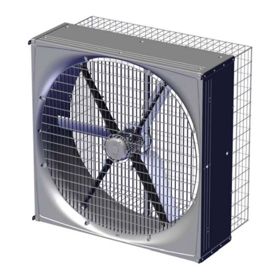
BF 50 recirculation is a direct-driven corrosion-resistant recirculation fan. BF 50 recirculation is supplied without safety net - these can be ordered as accessories. The recirculation fan is available in several different versions focusing on low power consumption, as well as standard versions. -
Page 7: Product Survey
BF 50 Recirculation 2 Product survey 2.1 BF 50 recirculation fan 2.1.1 Type key BF 50 ON/OFF recirc. 400V3 50Hz 1.5hp Fan name Blue fan Fan size Impeller diameter in inches” Fan type ON/OFF AC fan LPC fan Rated voltage... - Page 8 BF 50 Recirculation 435453 BF 50 LPC recirc. LE 230V1 50/60Hz Safety net must be mounted to comply with CE marking, in countries where this is required. LPC motor controller PM motor 1.5 kW. 0.7 m motor cable. Is supplied assembled without net.
-
Page 9: Accessories
435460 BF 50 mounting brackets f/recirculation The mounting bracket is used for recirculation where the fan hangs from the ceiling. Supplied with screws for mounting on the fan. SKOV A/S do not supply other mounting parts. One for each fan. - Page 10 BF 50 Recirculation 445076 LPC-2 relay module Used for mounting in motor controller/frequency converter, if an alarm out- put is required or reversing of fan is required. 1 x potential free output relay 1 A, 30 V DC/24 V AC.
-
Page 11: Mounting Guide
BF 50 Recirculation 3 Mounting guide 3.1 Recommended tools A list of the recommended tools for mounting purposes can be seen below. Item Description Cordless drill Screwdriver bits Drill kit Utility knife Marker pen Torque wrench Tape measure Combination spanner kit... -
Page 12: Removal Of Transport Bracket
BF 50 Recirculation 3.2 Removal of transport bracket On the recirculation fan the red transport bracket is placed between the impeller and the center pillar. Twist the transport bracket out from the center pillar. Remove transport brackets from the fan. -
Page 13: Mounting Of Accessories
BF 50 Recirculation 3.3 Mounting of accessories 3.3.1 Mounting of bracket for recirculation Place the 4 brackets as shown. The two brackets that are similar must be placed diagonally. Mark 6 holes for each of the 4 brackets. Pre-drill the 6 holes with a Ø4.8 mm drill. -
Page 14: Mounting Of Inside Safety Net
BF 50 Recirculation 3.3.2 Mounting of inside safety net If a safety net has not been selected, a safety guard must be established. The requirements of the International Standard for Safety of machinery ISO 13857 shall be complied with. Make sure that the net is turned as shown in the draw- ing. -
Page 15: Mounting Of Outside Safety Net
BF 50 Recirculation 3.3.3 Mounting of outside safety net If a safety net has not been selected, a safety guard must be established. The requirements of the International Standard for Safety of machinery ISO 13857 shall be complied with. Assemble the safety net outside with the included strips. -
Page 16: Installation Guide
In the case of retrofitting fans in an existing house, regardless of ON/OFF fans, LPC fans or frequency convert- ers SKOV recommends that a local expert is involved in checking the electrical installations. The focus should be on cable dimensions, overload protections, local transformers, etc. It is of outmost importance to take the fan specifications into account and, at the same time, ensure that local requirements are fulfilled. -
Page 17: Cabling To Connection Box And Lpc Motor Controller
BF 50 Recirculation 4.1.4 Cabling to connection box and LPC motor controller LPC motor controller Power supply isolator Example of cabling to connection box and LPC motor controller. Connection box 4.1.5 Cabeling and placement of LPC motor controller Motor controller must not be built-in or covered and must be mounted on a solid, level surface. -
Page 18: Connection In The Lpc Motor Controller/Frequency Converter
BF 50 Recirculation 4.2 Connection in the LPC motor controller/frequency converter Motor connection terminals (U, V, W, PE) Connection terminals for braking resistor (not used) Connector for optional module Terminal block for programming interface RJ12 programming connector (2 x slave / 1 x master) -
Page 19: Terminals For Power Supply
BF 50 Recirculation 4.2.1 Terminals for power supply Power supply 3 x 400 V / 3 x 230 V. Power supply 1 x 230 V. Technical User Guide... -
Page 20: Terminals For Supply Of The Fan Motor
BF 50 Recirculation 4.2.2 Terminals for supply of the fan motor Remember to strip the cable so that the protective shield from the fan can be connected to the motor controller during mounting under the rail. Connection from motor controller to fan motor. -
Page 21: Led Indication On The Motor Controller/Frequency Converter
BF 50 Recirculation 4.3 LED indication on the motor controller/frequency converter The motor controller/frequency converter is equipped with a two-color LED for indication of different operating modes. LED is located on the underside next to the cable glands. • Constantly green when mains voltage is connected. -
Page 22: General Information About Circuit Diagrams
BF 50 Recirculation Alarm overview External 24V DC supply over- loaded Supply voltage too high 4.5 General information about circuit diagrams Symbols are in accordance with the IEC/EN 60617 standard. The classification of the symbols ("letter codes") on the symbols is in accordance with the IEC/EN 81346-2 stan- dard. -
Page 23: Cable Plans And Circuit Diagrams
BF 50 Recirculation Protective equipment RCCB / Controller Power supply Switch Motor con- Cable Initial fuse Protective motor isolator troller Contactor Motor switch 4.6 Cable plans and circuit diagrams 4.6.1 BF 50 LPC recirculation 1x230 V 4.6.1.1 Cable plan Controller... -
Page 24: Circuit Diagram
BF 50 Recirculation 4.6.1.3 Circuit diagram Analog signal default 10-0 V, if you want to change the analog signal, see section Signal terminals [} 20] Example of terminal number For correct connection see the setup menu Show connection in controller Connection box... -
Page 25: Bf 50 Lpc Recirculation 3X400 V
BF 50 Recirculation 4.6.2 BF 50 LPC recirculation 3x400 V 4.6.2.1 Cable plan Controller LPC fan 3x400 V LPC motor controller Power supply Connection box isolator 4.6.2.2 Terminals in LPC 3x400 V fan Internal External Technical User Guide... -
Page 26: Circuit Diagram
BF 50 Recirculation 4.6.2.3 Circuit diagram Analog signal default 10-0 V, if you want to change the analog signal, see section Signal terminals [} 20] Example of terminal number For correct connection see the setup menu Show connection in the controller... -
Page 27: Bf 50 On/Off Recirculation 1X230 V
BF 50 Recirculation 4.6.3 BF 50 ON/OFF recirculation 1x230 V 4.6.3.1 Cable plan Controller Connection box ON/OFF fan 1 x 230 V Power supply isolator 4.6.3.2 Terminals in ON/OFF 1 x 230 V fan External Internal Technical User Guide... -
Page 28: Circuit Diagram
BF 50 Recirculation 4.6.3.3 Circuit diagram Example of terminal number For correct connection see the setup menu Show connection in controller Fan 1x230V Technical User Guide... -
Page 29: Bf 50 On/Off Recirculation 3X400 V
BF 50 Recirculation 4.6.4 BF 50 ON/OFF recirculation 3x400 V 4.6.4.1 Cable plan Controller Connection box ON/OFF fan 3x400 V Power supply isolator 4.6.4.2 Terminals in ON/OFF 3x400 V fan Internal External Technical User Guide... -
Page 30: Circuit Diagram
BF 50 Recirculation 4.6.4.3 Circuit diagram Example of terminal number For correct connection see the setup menu Show connections in the controller Fan 3x400V Technical User Guide... -
Page 31: Bf 50 On/Off Recirculation 3X230 V
BF 50 Recirculation 4.6.5 BF 50 ON/OFF recirculation 3x230 V 4.6.5.1 Cable plan Controller Connection box ON/OFF fan 3x230 V Power supply isolator 4.6.5.2 Terminals in ON/OFF 3x230 V fan Internal External Technical User Guide... -
Page 32: Circuit Diagram
BF 50 Recirculation 4.6.5.3 Circuit Diagram Example of terminal number For correct connection see the setup menu Show connection in controller Fan 3x230V Technical User Guide... -
Page 33: Maintenance Instructions
When washing the inside of the ducts, fan blades must stand still. Remember that fans do not stand high-pressure cleaning. If the inside of the duct needs to be cleaned extra thoroughly SKOV A/S recommends washing from above. When washing the fan, the fan must run around. -
Page 34: Troubleshooting
BF 50 Recirculation 6 Troubleshooting Remember to shut the fan off at the power supply isolator prior to troubleshooting. Troubleshooting fan motor Fault symptom Status LED Error Solution Faulty mounting. Check in accordance with the docu- ment. Retighten if required. - Page 35 BF 50 Recirculation Troubleshooting LPC motor controller Fault symptom Status LED Error Solution Stopped after 5 restart Wrong direction of rotation. Invert the rotation direction. attempts caused by the Phase error on the motor sup- Measure the voltage going to the same error within 60 ply (U, V, W).
-
Page 36: Technical Data
BF 50 Recirculation 7 Technical data 7.1 BF 50 LPC recirculation 1x230 V 435453 BF 50 LPC recirc. LE 230V1 50/60Hz Electrical V AC 230 +/- 10% Rated voltage V AC 175 – 280 Operating voltage For supply voltages below the rated voltage range, a reduction of the fan’s RPM may occur depending on the load and ambient... - Page 37 BF 50 Recirculation 435453 BF 50 LPC recirc. LE 230V1 50/60Hz /kWh 3760 Specific output at 0 Pa Watt/1000 Specific energy at 0 Pa SKOV A/S Testing body Environment °C - 40 to + 40 Temperature, operation °C - 40 to + 50 Start temperature °C...
-
Page 38: Bf 50 Lpc Recirculation 3X400 V
BF 50 Recirculation 7.2 BF 50 LPC recirculation 3x400 V 435454 BF 50 LPC recirc. LE 400V3 50/60Hz Electrical V AC 400 +/- 10% Rated voltage V AC 280 – 485 Operating voltage For supply voltages below the rated voltage range, a reduction of the fan’s RPM may occur depending on the load and ambient... - Page 39 BF 50 Recirculation 435454 BF 50 LPC recirc. LE 400V3 50/60Hz SKOV A/S Testing body Environment °C - 40 to + 40 Temperature, operation °C - 40 to + 50 Start temperature °C - 40 to + 70 Storage temperature...
- Page 40 BF 50 Recirculation 7.3 BF 50 ON/OFF recirculation 1x230 V 435450 BF 50 ON/OFF recirc. 435451 BF 50 ON/OFF recirc. 230V1 1.5hp 50Hz 230V1 1.5hp 60Hz Electrical V AC 230 +/-10% Rated voltage V AC 207 - 253 Operating voltage Frequency 6.30...
- Page 41 BF 50 Recirculation 7.4 BF 50 ON/OFF recirculation 3x400 V 435452 BF 50 ON/OFF recirc. 400V3 1.5hp 50Hz Electrical V AC 400 +/-10% Rated voltage V AC 360 – 440 Operating voltage Frequency 2.80 Max. current consumption At 400 V AC supply 1405 Max.
- Page 42 BF 50 Recirculation 7.5 BF 50 ON/OFF recirculation 3x230 V 435448 BF 50 ON/OFF recirc. 230V3 1.5hp 60Hz Electrical V AC 230 +/-10% Rated voltage V AC 207 - 253 Operating voltage Frequency 4.83 Max. current consumption At 230 V AC supply 1344 Max.
-
Page 43: Dimensioned Sketch
BF 50 Recirculation 7.6 Dimensioned sketch 7.6.1 BF 50 recirculation 7.6.2 Outside safety net Outside safety net Technical User Guide... -
Page 44: Lpc Motor Controller
BF 50 Recirculation 7.6.3 LPC motor controller 1x230 V 3x230 V and 3x400 V Technical User Guide... - Page 48 SKOV A/S • Hedelund 4 • Glyngøre • DK-7870 Roslev Tel. +45 72 17 55 55 • www.skov.com • E-mail: skov@skov.dk...
Need help?
Do you have a question about the BF 50 Recirculation and is the answer not in the manual?
Questions and answers