Table of Contents
Advertisement
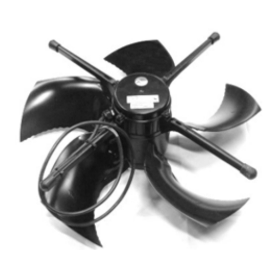
DA 600 LPC • DA 600 • ECT
632-6 • DCT 632-6
Fans
Technical User Guide
English For other language variants of this document we refer to:
Español Para otras variantes del idioma de este documento, visite:
Français Pour les versions dans d'autres langues de ce document veuillez consulter:
http://docs.skov.com/1051
613051 • 2022-10-18
Advertisement
Table of Contents

Subscribe to Our Youtube Channel
Related Manuals for Skov DA 600 LPC


Summary of Contents for Skov DA 600 LPC
- Page 1 DA 600 LPC • DA 600 • ECT 632-6 • DCT 632-6 Fans Technical User Guide English For other language variants of this document we refer to: Español Para otras variantes del idioma de este documento, visite: Français Pour les versions dans d'autres langues de ce document veuillez consulter: http://docs.skov.com/1051...
- Page 2 Note • All rights belong to SKOV A/S. No part of this manual may be reproduced in any manner whatsoever without the expressed written permission of SKOV A/S in each case.
-
Page 3: Table Of Contents
Terminals in DA 74CO ....................... 30 4.7.3.4 Circuit diagram .......................... 30 4.7.4 DA 600 LPC 230 V with thermal cutout and DA 74CO ON/OFF .......... 31 4.7.4.1 Cable plan.......................... 31 4.7.4.2 Terminals in LPC 230 V fan with thermal cutout................ 31 4.7.4.3... - Page 4 Terminals in DA 74CV ....................... 34 4.7.5.4 Circuit diagram .......................... 34 4.7.6 DA 600 LPC 230 V with thermal cutout and DA 74CV stepless .......... 35 4.7.6.1 Cable plan.......................... 35 4.7.6.2 Terminals in LPC 230 V fan with thermal cutout................ 35 4.7.6.3...
-
Page 5: Product Description
DA 600 LPC • DA 600 • ECT 632-6 • DCT 632-6 1 Product description An LPC fan is an energy efficient fan unit consisting of a PM motor with matching motor control and opimised wing design for LPC (Low Power Consumperion) and Dynamic MultiStep systems. -
Page 6: Product Survey
The fan comes with a 2-meter cable for the wiring between motor and motor controller. 445927 DA 600 LPC cable set 5m can be ordered, if 2m is insufficient. The power supply to the motor controller does not require a shielded cable. -
Page 7: Lpc Accessories
DA 600 LPC • DA 600 • ECT 632-6 • DCT 632-6 2.2 LPC accessories 409145 Thermal protection for fan 230 V with alarm contact 409147 Thermal protection for fan 400 V with alarm contact For the protection of a LPC fan with thermal cutout. - Page 8 DA 600 LPC • DA 600 • ECT 632-6 • DCT 632-6 2.3 DA 600 445090 DA - 600-7 ON/OFF fan 400V3 50Hz Three fan blades, 3x400 V fans with PAG fan blades. It cannot be Triac regulated, and it is therefore used as an ON/OFF fan.
-
Page 9: Ect/Dct 632-6
DA 600 LPC • DA 600 • ECT 632-6 • DCT 632-6 445099 DA - 600-7 ON/OFF fan 230V3 50Hz Three fan blades, 3x230 V fans with PAG fan blades. It cannot be Triac regulated, and it is therefore used as an ON/OFF fan. - Page 10 DA 600 LPC • DA 600 • ECT 632-6 • DCT 632-6 409146 ECT 632-6 Triac/ON/OFF 230V1 60 Hz cUL Five fan blades, 1x230 V, 60 Hz adjustable fan with aluminium fan blades. Can be used both as a stepless triac controlled fan and as an ON/OFF fan.
-
Page 11: Mounting Guide
DA 600 LPC • DA 600 • ECT 632-6 • DCT 632-6 3 Mounting guide 3.1 Recommended tools A list of the recommended tools for mounting purposes can be seen below. Item Description Cordless drill Screwdriver bits Drill kit Multimeter... -
Page 12: Positioning Of The Fan In The Exhaust Unit
DA 600 LPC • DA 600 • ECT 632-6 • DCT 632-6 3.2 Positioning of the fan in the exhaust unit The connection box on the fan must face downwards when the fan is used as a wall exhaustion. Mount the four fan suspensions using 6 x 25 screws in the marked positions. -
Page 13: Safety Distance
DA 600 LPC • DA 600 • ECT 632-6 • DCT 632-6 3.3 Safety distance If the distance from the floor to the fan blade is less than 270cm, mounting a protective mesh in the inlet bell mouth may be required to meet the statutory require- ments. -
Page 14: Position Of Motor Controller/Frequency Converter
DA 600 LPC • DA 600 • ECT 632-6 • DCT 632-6 3.6 Position of motor controller/frequency converter The motor controller/frequency converter is positioned so that the ambient temperature is between ÷ 40 °C and + 50 °C. Mount the motor controller/frequency converter as close to the fan as possible. -
Page 15: Installation Guide
In the case of retrofitting fans in an existing house, regardless of ON/OFF fans, LPC fans or frequency convert- ers SKOV recommends that a local expert is involved in checking the electrical installations. The focus should be on cable dimensions, overload protections, local transformers, etc. It is of outmost importance to take the fan specifications into account and, at the same time, ensure that local requirements are fulfilled. -
Page 16: Cabling Into The Motor Controller/Frequency Converter
DA 600 LPC • DA 600 • ECT 632-6 • DCT 632-6 4.1.4 Cabling into the motor controller/frequency converter In order to prevent water from running into the motor controller/frequency converter via cables and screwed connections, the cabling must be carried out so that it can stand water around the cable in the gasket of the screwed connection. -
Page 17: Connection In The Lpc Motor Controller/Frequency Converter
DA 600 LPC • DA 600 • ECT 632-6 • DCT 632-6 4.2 Connection in the LPC motor controller/frequency converter Motor connection terminals (U, V, W, PE) Connection terminals for braking resistor (not used) Connector for optional module Terminal block for programming interface... -
Page 18: Terminals For Power Supply
DA 600 LPC • DA 600 • ECT 632-6 • DCT 632-6 4.2.1 Terminals for power supply Power supply 3 x 400 V / 3 x 230 V. Power supply 1 x 230 V. Technical User Guide... -
Page 19: Terminals For Supply Of The Fan Motor
DA 600 LPC • DA 600 • ECT 632-6 • DCT 632-6 4.2.2 Terminals for supply of the fan motor Remember to strip the cable so that the protective shield from the fan can be connected to the motor controller during mounting under the rail. -
Page 20: Terminals On Relay Module
DA 600 LPC • DA 600 • ECT 632-6 • DCT 632-6 4.2.4 Terminals on relay module Relay module 445076 can be purchased as accessories. Ground Normal = open Reverse = GND (Short-circuit connection between terminal 15 and GND) Not in use Alarm NO Max. -
Page 21: Led Indication On The Motor Controller/Frequency Converter
DA 600 LPC • DA 600 • ECT 632-6 • DCT 632-6 4.3 LED indication on the motor controller/frequency converter The motor controller/frequency converter is equipped with a two-color LED for indication of different operating modes. LED is located on the underside next to the cable glands. -
Page 22: Adjusting The Jumper And Connecting The Shutter
DA 600 LPC • DA 600 • ECT 632-6 • DCT 632-6 Alarm overview External 24V DC supply over- loaded Supply voltage too high 4.5 Adjusting the jumper and connecting the shutter Set the jumper on the PCB to give actuator the desired function. -
Page 23: General Information About Circuit Diagrams
DA 600 LPC • DA 600 • ECT 632-6 • DCT 632-6 4.6 General information about circuit diagrams Symbols are in accordance with the IEC/EN 60617 standard. The classification of the symbols ("letter codes") on the symbols is in accordance with the IEC/EN 81346-2 stan- dard. -
Page 24: Cable Plans And Circuit Diagrams
DA 600 LPC • DA 600 • ECT 632-6 • DCT 632-6 4.7 Cable Plans and Circuit Diagrams 4.7.1 Circuit diagrams for OFF/AUTO/ON switch 4.7.1.1 Control voltage (LPC with DA 74CO) Example of terminal number For correct connection see the setup menu... -
Page 25: Control Voltage (Lpc With Da 74Cv)
DA 600 LPC • DA 600 • ECT 632-6 • DCT 632-6 4.7.1.2 Control voltage (LPC with DA 74CV) Example of terminal number For correct connection see the setup menu Show connection in controller Winch motor stepless Technical User Guide... -
Page 26: Control Voltage (On/Off With Da 74Co)
DA 600 LPC • DA 600 • ECT 632-6 • DCT 632-6 4.7.1.3 Control voltage (ON/OFF with DA 74CO) Example of terminal number For correct connection see the setup menu Show connection in controller Winch motor ON/OFF Technical User Guide... -
Page 27: 600 Lpc-2
DA 600 LPC • DA 600 • ECT 632-6 • DCT 632-6 4.7.2 DA 600 LPC-2 4.7.2.1 Cable plan 4.7.2.2 Terminals in LPC 230 V fan Technical User Guide... -
Page 28: Circuit Diagram
DA 600 LPC • DA 600 • ECT 632-6 • DCT 632-6 4.7.2.3 Circuit diagram Example of terminal number For correct connection see the setup menu Show connection in controller LPC motor controller LPC fan Technical User Guide... -
Page 29: 600 Lpc 230 V With Da 74Co On/Off
DA 600 LPC • DA 600 • ECT 632-6 • DCT 632-6 4.7.3 DA 600 LPC 230 V with DA 74CO ON/OFF 4.7.3.1 Cable plan 4.7.3.2 Terminals in LPC 230 V fan Technical User Guide... -
Page 30: Terminals In Da 74Co
DA 600 LPC • DA 600 • ECT 632-6 • DCT 632-6 4.7.3.3 Terminals in DA 74CO 4.7.3.4 Circuit diagram Power supply from emergency opening 0V = Q1 terminal in controller Power supply from emergency opening 24V-1 = Q2, Q3, Q4 and Q5 terminal in controller. -
Page 31: 600 Lpc 230 V With Thermal Cutout And Da 74Co On/Off
DA 600 LPC • DA 600 • ECT 632-6 • DCT 632-6 4.7.4 DA 600 LPC 230 V with thermal cutout and DA 74CO ON/OFF 4.7.4.1 Cable plan 4.7.4.2 Terminals in LPC 230 V fan with thermal cutout Technical User Guide... -
Page 32: Terminals In Da 74Co
DA 600 LPC • DA 600 • ECT 632-6 • DCT 632-6 4.7.4.3 Terminals in DA 74CO 4.7.4.4 Circuit diagram Power supply from emergency opening 0V = Q1 terminal in controller Power supply from emergency opening 24V-1 = Q2, Q3, Q4 and Q5 terminal in controller. -
Page 33: 600 Lpc 230 V With Da 74Cv Stepless
DA 600 LPC • DA 600 • ECT 632-6 • DCT 632-6 4.7.5 DA 600 LPC 230 V with DA 74CV stepless 4.7.5.1 Cable plan 4.7.5.2 Terminals in LPC 230 V fan Technical User Guide... -
Page 34: Terminals In Da 74Cv
DA 600 LPC • DA 600 • ECT 632-6 • DCT 632-6 4.7.5.3 Terminals in DA 74CV 4.7.5.4 Circuit diagram Power supply from emergency opening 0V = Q1 terminal in controller Power supply from emergency opening 24V-1 = Q2, Q3, Q4 and Q5 terminal in controller. -
Page 35: 600 Lpc 230 V With Thermal Cutout And Da 74Cv Stepless
DA 600 LPC • DA 600 • ECT 632-6 • DCT 632-6 4.7.6 DA 600 LPC 230 V with thermal cutout and DA 74CV stepless 4.7.6.1 Cable plan 4.7.6.2 Terminals in LPC 230 V fan with thermal cutout Technical User Guide... -
Page 36: Terminals In Da 74Cv
DA 600 LPC • DA 600 • ECT 632-6 • DCT 632-6 4.7.6.3 Terminals in DA 74CV 4.7.6.4 Circuit diagram Power supply from emergency opening 0V = Q1 terminal in controller Power supply from emergency opening 24V-1 = Q2, Q3, Q4 and Q5 terminal in controller. -
Page 37: 600 Lpc/Da 74Cv Stepless With Reverse
DA 600 LPC • DA 600 • ECT 632-6 • DCT 632-6 4.7.7 DA 600 LPC/DA 74CV stepless with reverse 4.7.7.1 Cable plan Technical User Guide... -
Page 38: Circuit Diagram
DA 600 LPC • DA 600 • ECT 632-6 • DCT 632-6 4.7.7.2 Circuit diagram Power supply from emergency opening 0V = Q1 terminal in controller Power supply from emergency opening 24V-1 = Q2, Q3, Q4 and Q5 terminal in controller. -
Page 39: 600 Lpc/Da 74Cv Stepless With Alarm Relay
DA 600 LPC • DA 600 • ECT 632-6 • DCT 632-6 4.7.8 DA 600 LPC/DA 74CV stepless with alarm relay 4.7.8.1 Cable plan Technical User Guide... -
Page 40: Circuit Diagram
DA 600 LPC • DA 600 • ECT 632-6 • DCT 632-6 4.7.8.2 Circuit diagram Power supply from emergency opening 0V = Q1 terminal in controller Power supply from emergency opening 24V-1 = Q2, Q3, Q4 and Q5 terminal in controller. -
Page 41: 600 On/Off 400 V With Da 74Co On/Off
DA 600 LPC • DA 600 • ECT 632-6 • DCT 632-6 4.7.9 DA 600 ON/OFF 400 V with DA 74CO ON/OFF 4.7.9.1 Cable plan 4.7.9.2 Terminals in ON/OFF fan 400 V Technical User Guide... -
Page 42: Terminals In Da 74Co 400 V
DA 600 LPC • DA 600 • ECT 632-6 • DCT 632-6 4.7.9.3 Terminals in DA 74CO 400 V 4.7.9.4 Circuit diagram Power supply from emergency opening V0 = Q1 terminal in controller. Power supply from emergency opening 24V-1 = Q2, Q3, Q4 and Q5 terminal in controller. -
Page 43: 600 On/Off 230 V With Da 74Co On/Off
DA 600 LPC • DA 600 • ECT 632-6 • DCT 632-6 4.7.10 DA 600 ON/OFF 230 V with DA 74CO ON/OFF 4.7.10.1 Cable plan 4.7.10.2 Terminals in ON/OFF fan 3x230 V 60 Hz Technical User Guide... -
Page 44: Terminals In Da 74Co 3X230 V
DA 600 LPC • DA 600 • ECT 632-6 • DCT 632-6 4.7.10.3 Terminals in DA 74CO 3x230 V 4.7.10.4 Circuit diagram Power supply from emergency opening V0 = Q1 terminal in controller. Power supply from emergency opening 24V-1 = Q2, Q3, Q4 and Q5 terminal in controller. -
Page 45: 600 On/Off 230 V With Da 74Co On/Off
DA 600 LPC • DA 600 • ECT 632-6 • DCT 632-6 4.7.11 DA 600 ON/OFF 230 V with DA 74CO ON/OFF 4.7.11.1 Cable plan 4.7.11.2 Terminals in ON/OFF fan 3x230 V 50 Hz Technical User Guide... -
Page 46: Terminals In Da 74Co 3X230 V
DA 600 LPC • DA 600 • ECT 632-6 • DCT 632-6 4.7.11.3 Terminals in DA 74CO 3x230 V 4.7.11.4 Circuit diagram Power supply from emergency opening V0 = Q1 terminal in controller. Power supply from emergency opening 24V-1 = Q2, Q3, Q4 and Q5 terminal in controller. -
Page 47: Ect 632-6 On/Off 230 V With Da 74Co On/Off
DA 600 LPC • DA 600 • ECT 632-6 • DCT 632-6 4.7.12 ECT 632-6 ON/OFF 230 V with DA 74CO ON/OFF 4.7.12.1 Cable plan 4.7.12.2 Terminals in ECT fan 230 V ECT 632-6 230 V 50 Hz ECT 632-6 230 V 60 Hz... -
Page 48: Terminals In Da 74Co 230 V
DA 600 LPC • DA 600 • ECT 632-6 • DCT 632-6 4.7.12.3 Terminals in DA 74CO 230 V 4.7.12.4 Circuit diagram Power supply from emergency opening V0 = Q1 terminal in controller. Power supply from emergency opening 24V-1 = Q2, Q3, Q4 and Q5 terminal in controller. -
Page 49: Dct 632-6 On/Off 400 V With Da 74Co On/Off
DA 600 LPC • DA 600 • ECT 632-6 • DCT 632-6 4.7.13 DCT 632-6 ON/OFF 400 V with DA 74CO ON/OFF 4.7.13.1 Cable plan 4.7.13.2 Terminals in DCT fan Technical User Guide... -
Page 50: Terminals In Da 74Co 400 V
DA 600 LPC • DA 600 • ECT 632-6 • DCT 632-6 4.7.13.3 Terminals in DA 74CO 400 V 4.7.13.4 Circuit diagram Power supply from emergency opening V0 = Q1 terminal in controller. Power supply from emergency opening 24V-1 = Q2, Q3, Q4 and Q5 terminal in controller. -
Page 51: Maintenance Instructions
When washing the inside of the ducts, fan blades must stand still. Remember that fans do not stand high-pressure cleaning. If the inside of the duct needs to be cleaned extra thoroughly SKOV A/S recommends washing from above. When washing the fan, the fan must run around. -
Page 52: Troubleshooting Guide
DA 600 LPC • DA 600 • ECT 632-6 • DCT 632-6 6 Troubleshooting guide Remember to shut the fan off at the power supply isolator prior to troubleshooting. Troubleshooting flap system LPC/motor response Status LED Error Solution Flap touches the ventilation Remedy the damage. - Page 53 DA 600 LPC • DA 600 • ECT 632-6 • DCT 632-6 Troubleshooting fan motor Fault symptom Status LED Error Solution AC motor: Measure the voltage going to the motor. Power supply to the motor LPC motor: See Troubleshooting LPC mo-...
-
Page 54: Technical Data
DA 600 LPC • DA 600 • ECT 632-6 • DCT 632-6 7 Technical data 7.1 DA 600 LPC 445070/445073 445072/445075 DA 600 LPC-11-2 DA 600 LPC-13-2 Electrical V AC 230 ± 10 % Rated voltage V AC 175 – 280... - Page 55 DA 600 LPC • DA 600 • ECT 632-6 • DCT 632-6 445070/445073 445072/445075 DA 600 LPC-11-2 DA 600 LPC-13-2 Fan output 300-1100 300-1300 Revolutions (rated current) per minute 13900 16100 Air output at 0 Pa 13600 15800 Air output at -10 Pa...
-
Page 56: Erp/Ecodesign
DA 600 LPC • DA 600 • ECT 632-6 • DCT 632-6 7.1.1 ErP/Ecodesign Fan type DA 600 DA 600 DA 600 DA 600 LPC-11-2 LPC-11-2 LPC-13-2 LPC-13-2 w/thermal cutout w/thermal cutout ErP 2015 (58) Ecodesign 73.6 Efficiency classification 69.8 66.6... - Page 57 DA 600 LPC • DA 600 • ECT 632-6 • DCT 632-6 7.2 DA 600 445085 445099 445098 445090 DA 600-7F-2 DA 600-7-2 DA 600-7-2 DA 600-7-2 Electrical V AC 1x230 ± 10% 3x200 -5 % +10 / 3x230 ± 10 % 3x400 ±...
- Page 58 DA 600 LPC • DA 600 • ECT 632-6 • DCT 632-6 445085 445099 445098 445090 DA 600-7F-2 DA 600-7-2 DA 600-7-2 DA 600-7-2 16100 15200 14800 16600 Air output at -10 Pa 15900 14900 14400 16200 Air output at -20 Pa...
-
Page 59: Erp/Ecodesign
DA 600 LPC • DA 600 • ECT 632-6 • DCT 632-6 7.2.1 ErP/Ecodesign Fan type DA 600-7F-2 DA 600-7-2 DA 600-7-2 DA 600-7-2 ErP 2015 (N58) Ecodesign 63.2 68.8 60.1 64.2 Efficiency classification 52.2 62.3 53.2 57.9 Efficiency (η) -
Page 60: Ect/Dct 632-6
DA 600 LPC • DA 600 • ECT 632-6 • DCT 632-6 7.3 ECT/DCT 632-6 409143 409146 409144 ECT 632-6 ECT 632-6 CSA DCT 632-6 Electrical V AC 1x230 ± 10% 3x400 ± 10% Rated voltage V AC 207 – 253 360 –... -
Page 61: Erp/Ecodesign
DA 600 LPC • DA 600 • ECT 632-6 • DCT 632-6 409143 409146 409144 ECT 632-6 ECT 632-6 CSA DCT 632-6 % RH Ambient humidity, opera- tion Protection class dB (A) Fan noise, outside (2 m, 45 degrees) Shipment... -
Page 62: Dimensioned Sketch
DA 600 LPC • DA 600 • ECT 632-6 • DCT 632-6 7.4 Dimensioned sketch 7.4.1 DA 600 LPC LPC motor controller LPC fan Technical User Guide... -
Page 63: Ect/Dct 632-6
DA 600 LPC • DA 600 • ECT 632-6 • DCT 632-6 7.4.2 DA 600 DA 600-7-2 3x400 V 50 Hz / DA 600-7-2 3x230 V 60 Hz / DA 600-7F-2 1x230V 50 Hz DA 600-7-2 3x230 V 50 Hz 7.4.3 ECT/DCT 632-6... - Page 64 SKOV A/S • Hedelund 4 • Glyngøre • DK-7870 Roslev Tel. +45 72 17 55 55 • www.skov.com • E-mail: skov@skov.dk...
Need help?
Do you have a question about the DA 600 LPC and is the answer not in the manual?
Questions and answers