
Subscribe to Our Youtube Channel
Related Manuals for Nakanishi CTS-2630


Summary of Contents for Nakanishi CTS-2630
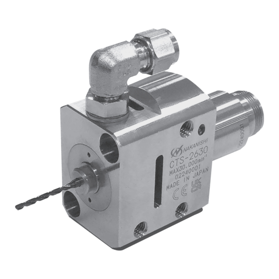
- Page 1 OM-KK1003MA 000 クーラントスルースピンドル / Coolant Through Spindle CTS - 2630 取扱説明書 / OPERATION MANUAL 日本語 : P1 - P19 / English : P21 - P40...
-
Page 2: Table Of Contents
Thank you for purchasing Coolant Through Spindle CTS-2630. This spindle is designed for use with small-diameter cutting drills with a coolant hole. The E3000 <CONTROLLER>, EM-3030T <Motor> and <Air Line Kit> are required to drive this spindle. Read this and all the associated component Operation Manuals carefully before use. - Page 3 WARNING (1) The spindle is not a hand tool. It is designed to be installed and used in machine tools or special purpose machines. (2) Do not touch the cutting tool while it is running. It is very dangerous. (3) Wear safety glasses and a dust mask, and use a protective cover around the spindle whenever the spindle is rotating.
- Page 4 CAUTION (1) A supply of coolant is required when using this spindle. If the spindle is used without supplying coolant, the generated heat could damage the components. (2) Use coolant with an ISO viscosity grade of VG22 or lower. (3) Do not drop or hit the spindle, as shock can damage the internal components. (4)...
-
Page 5: Basic Package
2. BASIC PACKAGE When opening the package, check if it includes all items listed in"Table. 1 Packing List Contents". In the event of any shortage, please contact either NAKANISHI (refer to section "4. CONTACT US") or your local dealer. Table. 1 Packing List Contents Spindle ·... -
Page 6: Warranty
(closed Saturday, Sunday and Public Holidays) Telephone No. : +81 289 64 3520 e-mail : webmaster-ie@nsk-nakanishi.co.jp 5. FEATURES (1) Coolant can be supplied and discharged from a cutting drill with a coolant hole, enabling deep hole drilling and high-efficiency machining. -
Page 7: Specifications And Dimensions
6. SPECIFICATIONS AND DIMENSIONS 6 - 1 Specifications Model CTS-2630 Max RPM 30,000 min Spindle Accuracy Within 1 μm Applicable Motors EM-3030T-J / EM-3030T-J-2M, EM-3030T Weight 570 g Noise Level (at 1 m Distance) 60 dB (A) or less < Coolant specifications >... -
Page 8: Connection To The Motor
6 - 2 Outside View 49.5 (Tool insertion length) (35) Coolant supply port (φ6) Mounting hole (front) Through hole (φ6.5) × 2 Counterbore (φ10.5, depth 6) × 2 G1 / 8 threads (depth 10) Wrench flats Mounting hole (side) (4.3) (13)... -
Page 9: Changing The Drill
8. CHANGING THE DRILL WARNING If there is residual pressure in the high-pressure pump, the drill may pop out, resulting in injury. Make sure that there is no residual pressure before replacing the drill. CAUTION • Never tighten the collet nut without inserting a cutting drill in the collet. Excessively tightening the collet may damage the tabs that hold the collet in the collet nut, making it difficult to remove the collet from the spindle. -
Page 10: Replacing The Collet
9. REPLACING THE COLLET CAUTION • The collet and collet nut are consumable parts and will wear out with use. Replace the collet or collet nut if collet force decreases or there are signs of wear or scratches. • When installing the collet in the collet nut, make sure that the tabs of the collet nut are properly seated in the groove of the collet. -
Page 11: Installing The High-Pressure Pump, Coolant Hose And Fittings
10. INSTALLING THE HIGH-PRESSURE PUMP, COOLANT HOSE AND FITTINGS WARNING • When using coolant, check the operating pressure before connecting the coolant hose and fittings. If the maximum operating pressure of the coolant hose or fittings is exceeded, they could burst and cause injury. •... - Page 12 < Reference example of recommended items to prepare > Item Product Number (Example) Manufacturer High-pressure pump Hydro pump RIX CORPORATION ・ CHP150-1200 Intake filter, intake hose (CHP150-1200 accessory) RIX CORPORATION Filter Line filter Taisei Kogyo Co., Ltd. ・ TM-C-04-2-3CH High-pressure coolant hose NH hose ASK Corporation ・...
- Page 13 10 - 1 Installing and Connecting the High-pressure Pump (1) Install the manifold block so that it does not interfere with other components in the machine tool. (2) Install the high-pressure pump, and place the intake filter in the coolant tank of the machine tool. (3)...
- Page 14 10 - 2 Adjusting the High-pressure Coolant Fitting Angle (1) Loosen the lock nut of the high-pressure coolant Adjust the angle High-pressure fitting. coolant fitting (2) Adjust the high-pressure coolant fitting to an Lock nut angle at which the high-pressure coolant hose is easy to connect.
- Page 15 < Replacing the high-pressure coolant fitting > High-pressure coolant fitting Elbow surface (1) Loosen the lock nut of the high-pressure coolant fitting. (2) Fit an adjustable wrench on the elbow Lock nut surface (shaded area) of the high-pressure coolant fitting, and turn it counterclockwise Loosen to remove the high-pressure coolant fitting.
- Page 16 10 - 4 - 2 Reconnecting the Hose (1) Insert the high-pressure coolant hose (diameter φ6mm) so that the tapered surface of the ferrule set fastened to the high-pressure coolant hose (diameter φ6 mm) fits tightly against the tapered surface of the high-pressure coolant fitting. (Fig. 15) Tapered surface of high-pressure coolant fitting Tapered surface of ferrule set...
-
Page 17: Supplying The Coolant
11. SUPPLYING THE COOLANT CAUTION • A supply of coolant is required when using this spindle. If this spindle is used without supplying coolant, the generated heat could damage the components. • Use coolant with an ISO viscosity grade of VG 22 or lower. The lower the viscosity, the easier it is for the coolant to be released. - Page 18 < Using the mounting holes (front) > (1) Insert the spindle body housing (diameter φ26 mm) section into the fixed base of the machine tool. (2) Secure the spindle through the mounting holes (2 locations) using the fastening bolts (M6). (Fig. 18) <...
-
Page 19: Break-In Procedure
13. BREAK-IN PROCEDURE During transportation, storage or installation, the grease inside the bearings will settle. If the spindle is suddenly run at high-speed, excessive heat may cause bearing damage. Before operating for the first time after installation, repair, or a long period of non-operation, follow the break-in procedure detailed in steps 1 to 4 of Table. -
Page 20: Troubleshooting
Inspection / Corrective Action Spindle does not run. The ball bearings are Replace the ball bearings. damaged. (Return to NAKANISHI dealer service.) Motor is broken. Replace the motor. (Return to NAKANISHI dealer service.) Collet nut contact or Replace the collet nut. -
Page 21: Disposal Of The Spindle
16. DISPOSAL OF THE SPINDLE When disposal of this spindle is necessary, follow the instructions from your local government agency for proper disposal of industrial components.
Need help?
Do you have a question about the CTS-2630 and is the answer not in the manual?
Questions and answers